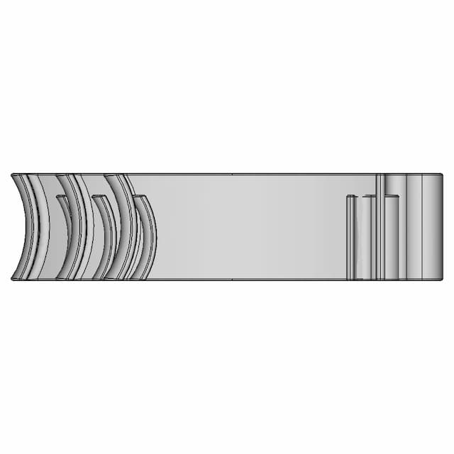
Standard conversions from live pricingLive pricingSTEP or STP to 2D drawings2D drawingsSee conversion pricingPricing
Marathon Logo
Why us?Dashboard
Library
Hire Designers
Tools
Resources
  1. Home /
  2. Library /
  3. 2D Technical Drawings /
  4. As5048A Magnetic Encoder 1 | Professional CAD Design
📐 2D Technical Drawings🤖 AI Generated

As5048A Magnetic Encoder 1 | Professional CAD Design 2D Technical Drawing Set

5
Drawing sheets
5
Views analysed
3
Export formats
2
Section cuts
1st Angle
Projection type
23 Jun 2026
Generated date
STEP
Source CAD format
As5048A Magnetic Encoder 1 | Professional CAD Design
Source 3D model
MPreview · 2D Drawing Sheets
1 / 5
⚠Verify critical dimensions against the source CAD model before using these drawings for manufacturing or production release. Download the FCStd file where available for the most accurate editable source.
Assembly - Front View
Download all drawing sheets
PDF5 sheets
SVG5 files
DXF5 files
🧊Open source 3D CAD model→
ℹ️

These are 2D engineering drawings derived from the 3D CAD geometry. Verify critical dimensions against the source model before manufacturing.

🤖

Views, section cuts, and detail areas were selected by AI based on analysis of 6 rendered views of the 3D model.

AI Drawing Analysis

What the AI Decided & Why

The cards below explain how the generated drawing outputs and assets connect to the final technical sheets.

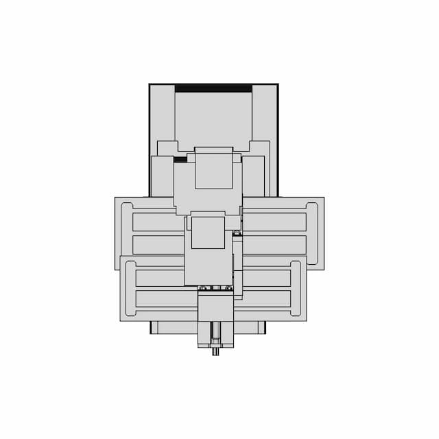
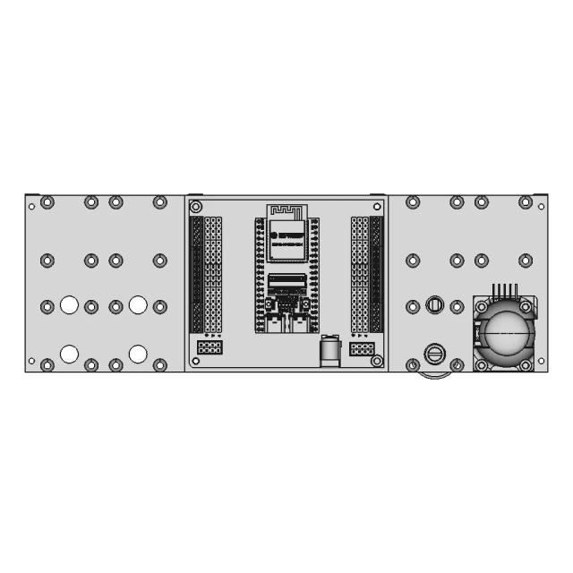
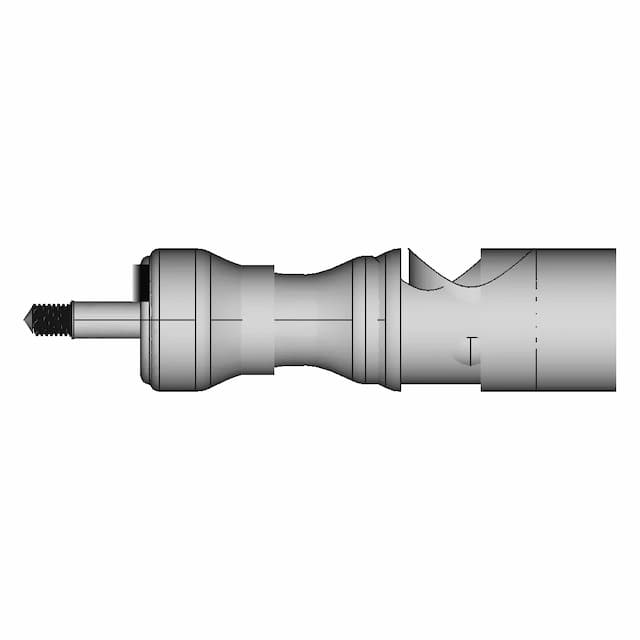
Assembly - Front View

Orthographic

The Front view clearly shows the primary mounting flange, the main shaft, and the internal structural frame, providing the most informative perspective of the encoder's functional interface.

Assembly - Top View

Orthographic

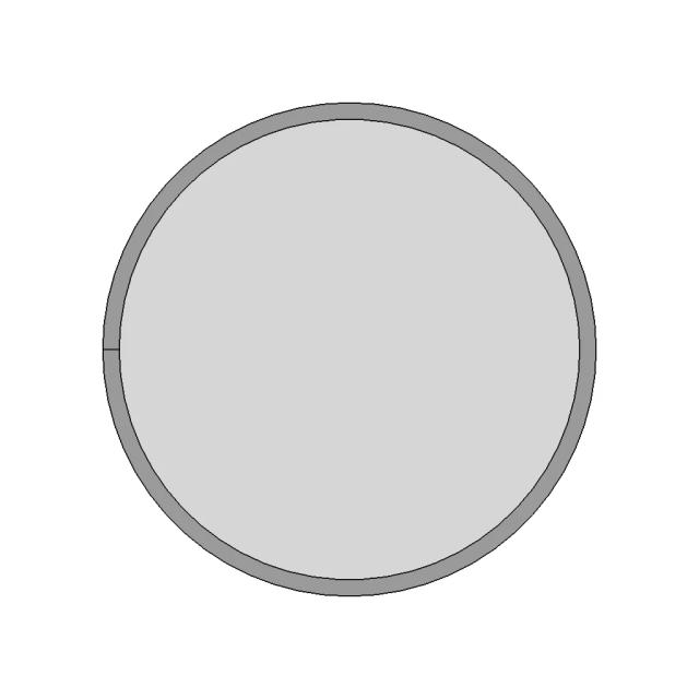
The Top view reveals the full footprint of the encoder, including the horizontal layout of the frame, the base, and the angled sensor arm, which is critical for understanding its overall size and installation.

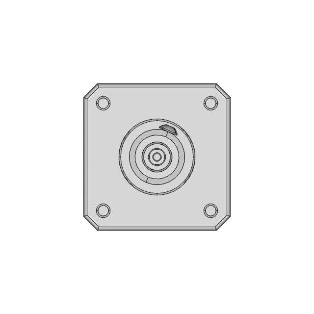
Assembly - Left View

Orthographic

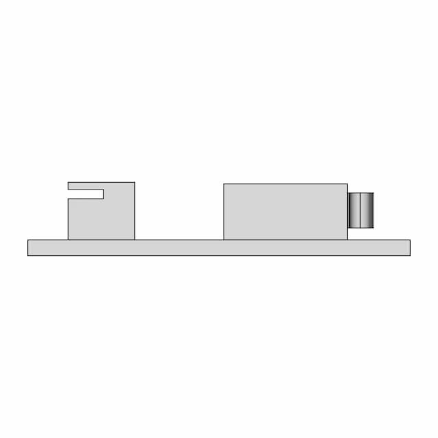
The Left view provides a side profile that clearly shows the depth of the assembly, the thickness of the mounting plate, and the vertical alignment of the internal components, which is not visible in the Front or Top views.

Section A-A

Orthographic

This section cut along the X-axis reveals the internal bore of the main shaft and the wall thickness of the mounting plate, which are critical for structural integrity and fit.

Section B-B

Orthographic

This horizontal section cut at the mid-plane shows the internal channel for the sensor arm and the thickness of the frame's cross-bracing, which are not visible from the outside.

A — Asection_a · Section5
sheet_num: 5 · edges: 19

This section cut along the X-axis reveals the internal bore of the main shaft and the wall thickness of the mounting plate, which are critical for structural integrity and fit.

  • 19 resolved edges in sheet geometry
  • See technical_drawing_simple.pdf, sheet_N.pdf, and svg/ for full graphical context
  • Verify critical dimensions against the source CAD before manufacturing
B — Bsection_b · Section6
sheet_num: 6 · edges: 25

This horizontal section cut at the mid-plane shows the internal channel for the sensor arm and the thickness of the frame's cross-bracing, which are not visible from the outside.

  • 25 resolved edges in sheet geometry
  • See technical_drawing_simple.pdf, sheet_N.pdf, and svg/ for full graphical context
  • Verify critical dimensions against the source CAD before manufacturing
Detail Cdetail_c · base_view: Front
anchor: (0, 776.393, -200) · radius: 15

This detail magnifies the critical bore of the main shaft, which is essential for the encoder's precision and must be manufactured to a specific tolerance.

  • Detail-view anchor selected by the AI planning stage
  • Use with sheet PDF/SVG for local feature inspection
  • Validate critical dimensions against source CAD before release
Detail Ddetail_d · base_view: Top
anchor: (185, 95, -270) · radius: 10

This detail shows the mounting hole pattern on the base, which is crucial for correct installation and alignment.

  • Detail-view anchor selected by the AI planning stage
  • Use with sheet PDF/SVG for local feature inspection
  • Validate critical dimensions against source CAD before release

Downloads

Download Individual Sheets

Each sheet available in PDF, SVG, and DXF. Click a format badge to download.

Assembly - Front View
Assembly - Top View
Assembly - Left View
Section A-A
Section B-B

Paid Pipeline · $5.99 per drawing set

Have your own 3D CAD file?

Upload a STEP or STP file and generate a 2D drawing set with PDF, SVG and DXF outputs.

  • ✓ Usually ready in minutes
  • ✓ 9 sheets · editable FCStd + PDF, SVG, DXF
  • ✓ No subscription · pay per file
$5.99
per drawing set incl. GST
4 min
avg. turnaround

AI Transparency

How these drawings were generated

These drawings were generated from the source 3D CAD geometry. The system analysed the model, selected relevant views, planned section cuts and generated drawing sheets in PDF, SVG and DXF formats.

These are 2D engineering drawings, not 3D files. Dimensions are extracted from the 3D geometry and should be verified against the source model before use in manufacturing.

Run Metadata

5
Views analysed
5
Sheets generated
2
Section cuts
3
Export formats
23 Jun 2026
Generated date

Explore Marathon OS

Related resources

Jump to the source 3D model, generate your own drawings, or browse tools and libraries.

Open source 3D CAD modelPreview the original 3D geometry used to generate these drawings→
Generate your own 2D drawingUpload STEP, STP, IGES or FreeCAD — get PDF, SVG and DXF→Browse more 2D technical drawingsExplore AI-generated orthographic sheets across part types→Browse 3D CAD modelsDownload and preview open-source STEP, STL and IGES files→Open CAD files onlineView STEP, IGES, STL and more in your browser→Convert CAD files onlineConvert between STEP, STL, OBJ and other 3D formats→Get manual drafting supportWork with vetted CAD designers for production-ready drawings→

Preview the Source 3D CAD Model

Open the original 3D CAD model used to generate this 2D drawing set. Review the source geometry before downloading or using the technical drawings.

Open 3D CAD model →
Marathon Logo

The specialist CAD conversion platform for engineering, mesh and drawing workflows.

Start a conversion
ConvertAll 60+ conversion toolsSTEP to STLSTL to STEPIGES to STEPDWG to DXFSTEP or STP to 2D
Products3D CAD Products2D CAD Products
Tools and servicesAll CAD Tools3D CAD ViewerSTEP BOM ExtractorHire a CAD Designer
CompanyHomeAbout UsContact Us
LegalPrivacy PolicyTerms and ConditionsRefund Policy
© 2026 Marathon OS. All rights reserved.Convert precisely. Download confidently. Keep moving.

Recently added / Trending

Everything you need to design faster, smarter, and with more impact.
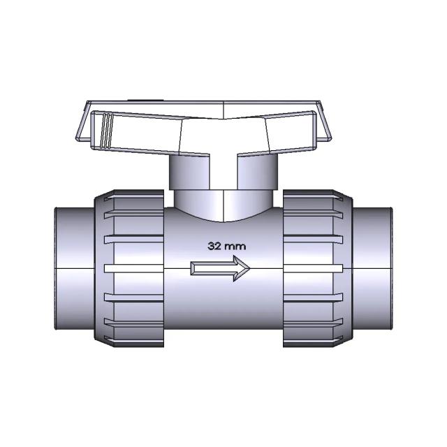
Ball Valve 32 mm
Ball Valve 32 mm
25Ga370 6V 35Rpm (171:1) Gear Motor - Downloadable CAD Representation
Bracelet 28 | Professional CAD Design
Double Valve Castel 3032 44
𝑹𝑨𝑫𝑰𝑨𝑻𝑶𝑹 𝑰𝑵𝑫𝑼𝑺𝑻𝑹𝑰𝑨𝑳 𝑯𝑬𝑨𝑻 𝑬𝑿𝑪𝑯𝑨𝑵𝑮𝑬𝑹 - Standard Mechanical Component
Honeywell RM 7800 Series Relay Module CAD Model
Ferrari 488 GTB Inspired Sports Car CAD Model
Clamp for Fitting Stainless Steel Pipes of Increased Pressure
Siemens S7-1200 PLC Solid Model for Engineering Applications
iPhone 16 Pro Max CAD Model
View all designs

Marathon-OS Design Hub

Everything you need to design faster, smarter, and with more impact.
Ice Cube Tray | 3D Engineering Design File
Test_001 | 3D Engineering Design File
Compact Toothbrush and Toothpaste Holder with Honeycomb Design
R36S Game Console Stand for Secure Tabletop Placement
Tripod 1 4 20 1 6Mm Styled Board Mount 1 | 3D CAD Engineering Model
Six Pointed Star 1 | 3D CAD Engineering Model
Minato S Flying Thunder God Kunai 1 | 3D CAD Engineering Model
Spool Holder Adapter 2 | 3D CAD Engineering Model
Ump9 1 | 3D CAD Engineering Model
Fdm 70Mm 1 | Professional CAD Design
Shooting Coin Holders 1 | 3D CAD Engineering Model
Nutcracker - Nussknacker | 3D Engineering Design File
Senal De Transito Rpo 14 1 | 3D CAD Engineering Model
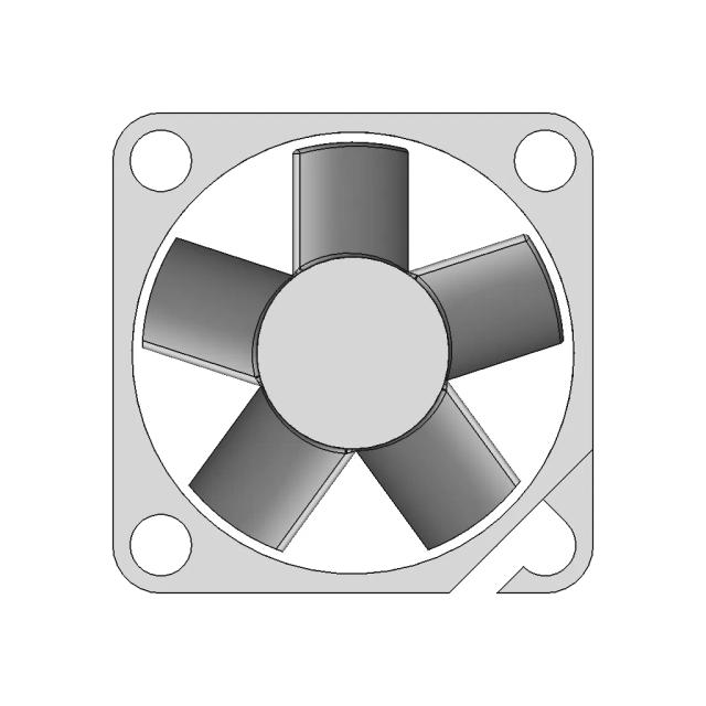
Sunon MagLev Brushless DC Motor Fan MF25100V1-1000U-A99
Box | 3D Engineering Design File
Mask Holder | 3D Engineering Design File
View all designs

Explore More 2D Designs

View all
BIO REACTOR, Used for CFD Analysis for Projects
2D Drawing$5.99
M12 X-CODE CAT6A Plug - High-Performance Industrial Connector
2D Drawing$5.99
M12 X-Code Connector - High-Performance Industrial Connector
2D Drawing$5.99
Toyota Hilux Double Cab 3D CAD Model for Engineering and Design
2D Drawing$5.99
Offroad Transmission Undershield for Enhanced Protection
2D Drawing$5.99
Adjustable Square and Round Tube Rock Slider for Pickup Trucks
2D Drawing$5.99
Aluminum Off-Road Front Bumper for Toyota Hilux Vigo
2D Drawing$5.99
Toyota Hilux Revo Offroad Bumper 4x4 Concept 3D Model
2D Drawing$5.99