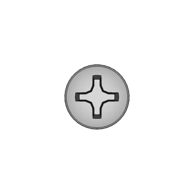
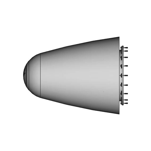
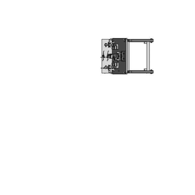
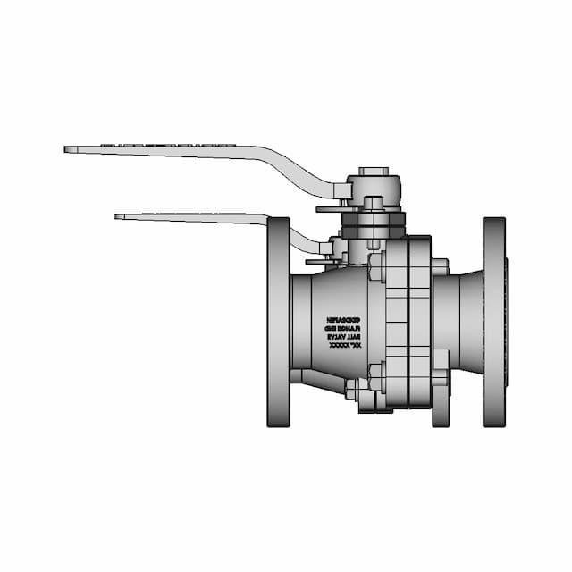
Standard conversions from live pricingLive pricingSTEP or STP to 2D drawings2D drawingsSee conversion pricingPricing
Marathon Logo
Why us?Dashboard
Library
Hire Designers
Tools
Resources
  1. Home /
  2. Library /
  3. 2D Technical Drawings /
  4. CAD Model of Robot Arm Gripper for Engineering Projects
📐 2D Technical Drawings🤖 AI Generated

CAD Model of Robot Arm Gripper for Engineering Projects 2D Technical Drawing Set

6
Drawing sheets
6
Views analysed
3
Export formats
1
Section cuts
1st Angle
Projection type
23 Aug 2026
Generated date
STEP
Source CAD format
CAD Model of Robot Arm Gripper for Engineering Projects
Source 3D model
MPreview · 2D Drawing Sheets
1 / 4
⚠Verify critical dimensions against the source CAD model before using these drawings for manufacturing or production release. Download the FCStd file where available for the most accurate editable source.
Sheet 1
Sheet 1
Download all drawing sheets
SVG4 files
DXF4 files
🧊Open source 3D CAD model→
ℹ️

These are 2D engineering drawings derived from the 3D CAD geometry. Verify critical dimensions against the source model before manufacturing.

🤖

Views, section cuts, and detail areas were selected by AI based on analysis of 6 rendered views of the 3D model.

AI Drawing Analysis

What the AI Decided & Why

The cards below explain how the generated drawing outputs and assets connect to the final technical sheets.

Sheet 1

Orthographic

This sheet includes 34 geometry edges from the CAD projection pipeline.

Sheet 2

Orthographic

This sheet includes 26 geometry edges from the CAD projection pipeline.

Sheet 3

Orthographic

This sheet includes 26 geometry edges from the CAD projection pipeline.

Sheet 5

Orthographic

This sheet includes 26 geometry edges from the CAD projection pipeline.

Sheet 5section_a · Section5
sheet_num: 5 · edges: 26

Sheet 5. Geometry is derived from the 3D model projection for this drawing set.

  • 26 resolved edges in sheet geometry
  • See technical_drawing_simple.pdf, sheet_N.pdf, and svg/ for full graphical context
  • Verify critical dimensions against the source CAD before manufacturing
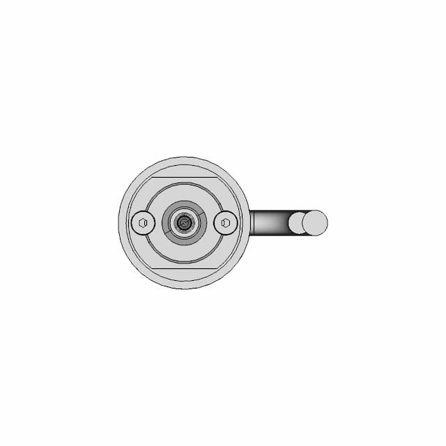
Detail Bdetail_b · base_view: Left
anchor: (160, 0, -83.5) · radius: 25

Magnifies the central bore and hexagonal fastener detail to clearly show the bore diameter, fastener type, and any internal threading or counterbore features.

  • Detail-view anchor selected by the AI planning stage
  • Use with sheet PDF/SVG for local feature inspection
  • Validate critical dimensions against source CAD before release

Downloads

Download Individual Sheets

Each sheet available in PDF, SVG, and DXF. Click a format badge to download.

Sheet 1
Sheet 2
Sheet 3
Sheet 5

Drawing report

Drawing details & review

Cover summary and review report for this versioned drawing set.

TECHNICAL DRAWING

680122c9b1f61b010dd05a5c

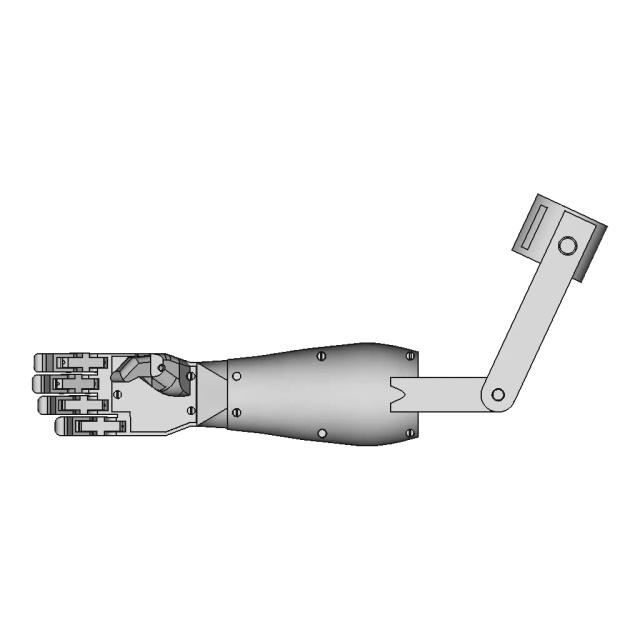
Robot Arm Gripper Assembly

6
sheets
0
control frames
0
dimensions not drawn
Sheet index
SheetViewScaleContent
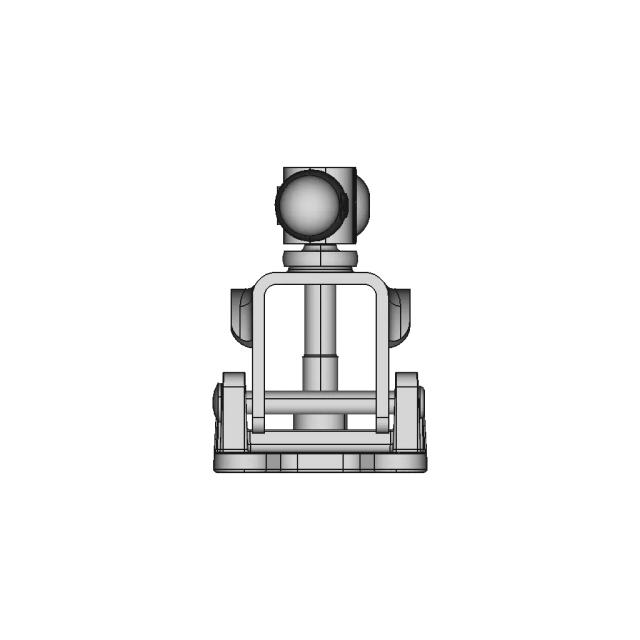
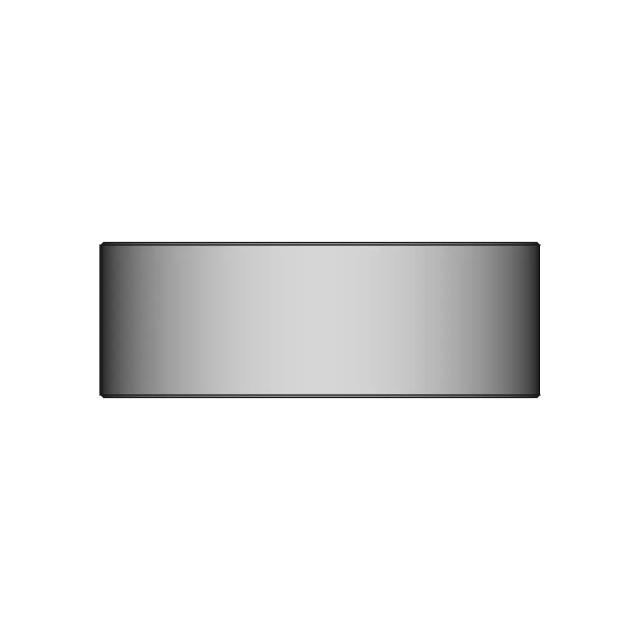
1Assembly - Front View2.0standard_view
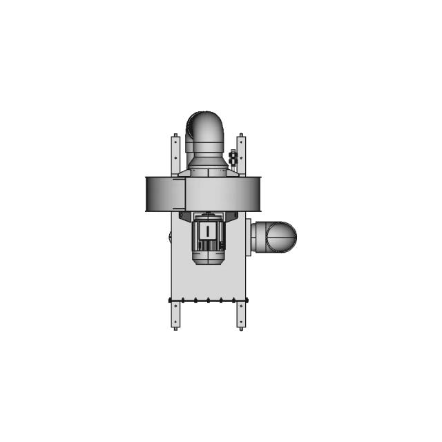
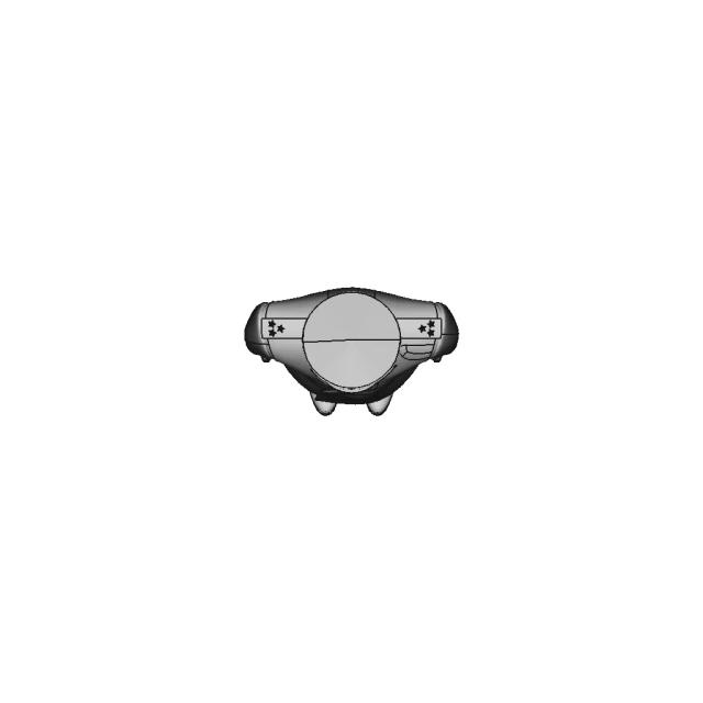
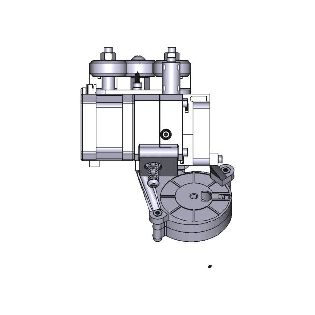
2Assembly - Top View2.0standard_view
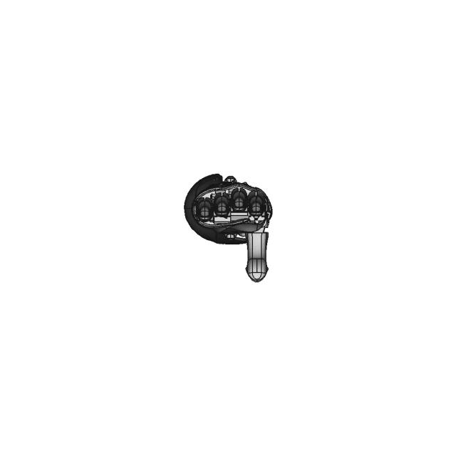
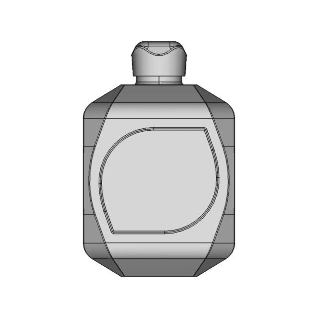
3Assembly - Left View2.0standard_view
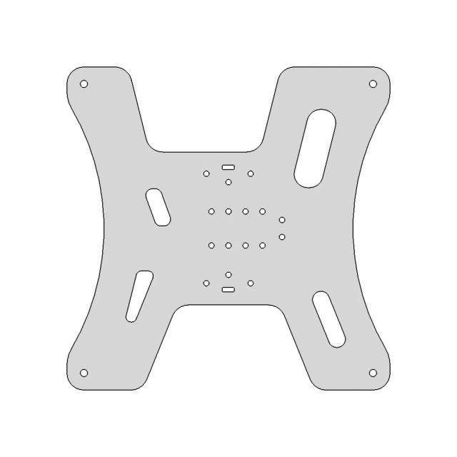
4Assembly - Isometric View2.0standard_view
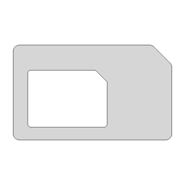
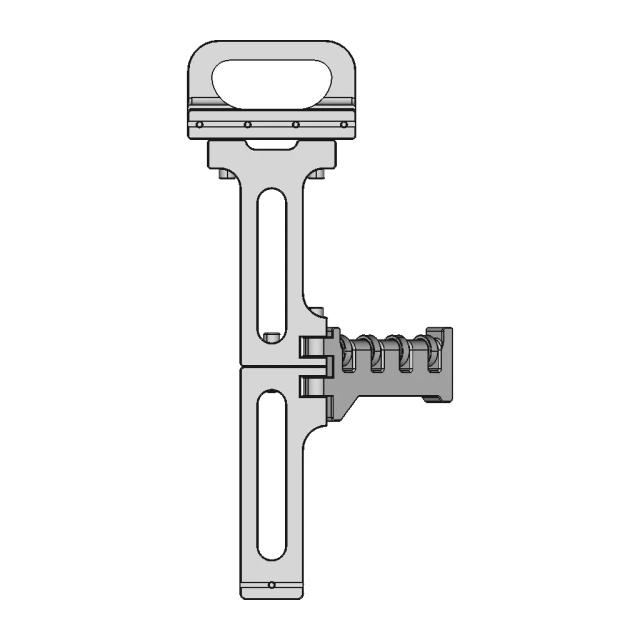
5Section A-A2.0section_view
6Detail B2.0detail_view

Generated automatically and intended for review before use. A companion review report lists what needs checking.

DRAWING REVIEW REPORT

680122c9b1f61b010dd05a5c

This drawing is generated automatically and is a first draft. The items below need a human decision.

Summary
30
dimensions drawn
0
selected, not drawn
0
control frames
0
assumed tolerances
Dimension schedule

All 30 dimension(s) drawn.

#SheetTypeValueDescription
11DistanceX258.2overall width 258.2mm
21Diameter8.012x Ø8.0mm
31Diameter15.62x Ø15.6mm
41DistanceY30.2hole pitch 30.2mm (vertical, Ø7.8)
51DistanceX42.6hole pitch 42.6mm (horizontal, Ø7.8)
61DistanceY77.9hole pitch 77.9mm (vertical, Ø15.6)
71Radius7.88x R7.8mm
81Radius9.72x R9.7mm
91Radius14.610x R14.6mm
101Radius97.49x R97.4mm
112DistanceX258.3overall width 258.3mm
122DistanceY51.6overall height 51.6mm
132Radius1.03x R1.0mm
142Radius1.33x R1.3mm
152Radius2.02x R2.0mm
162Radius2.413x R2.4mm
172Radius2.74x R2.7mm
182Radius3.76x R3.7mm
193DistanceX51.6overall width 51.6mm
203DistanceY167.1overall height 167.1mm
213Radius1.34x R1.3mm
223Radius2.417x R2.4mm
233Radius2.5R2.5mm
243Radius3.44x R3.4mm
253Radius3.66x R3.6mm
263Radius3.75x R3.7mm
275DistanceX51.6overall width 51.6mm
285Diameter10.1Ø10.1mm
295Radius2.44x R2.4mm
305Radius3.74x R3.7mm

Nothing to review: no dimensions were dropped and no control frames rest on an assumption.

Paid Pipeline · $5.99 per drawing set

Have your own 3D CAD file?

Upload a STEP or STP file and generate a 2D drawing set with PDF, SVG and DXF outputs.

  • ✓ Usually ready in minutes
  • ✓ 9 sheets · editable FCStd + PDF, SVG, DXF
  • ✓ No subscription · pay per file
$5.99
per drawing set incl. GST
4 min
avg. turnaround

AI Transparency

How these drawings were generated

These drawings were generated from the source 3D CAD geometry. The system analysed the model, selected relevant views, planned section cuts and generated drawing sheets in PDF, SVG and DXF formats.

These are 2D engineering drawings, not 3D files. Dimensions are extracted from the 3D geometry and should be verified against the source model before use in manufacturing.

Run Metadata

4
Views analysed
4
Sheets generated
1
Section cuts
2
Export formats
23 Aug 2026
Generated date

Explore Marathon OS

Related resources

Jump to the source 3D model, generate your own drawings, or browse tools and libraries.

Open source 3D CAD modelPreview the original 3D geometry used to generate these drawings→
Generate your own 2D drawingUpload STEP, STP, IGES or FreeCAD — get PDF, SVG and DXF→Browse more 2D technical drawingsExplore AI-generated orthographic sheets across part types→Browse 3D CAD modelsDownload and preview open-source STEP, STL and IGES files→Open CAD files onlineView STEP, IGES, STL and more in your browser→Convert CAD files onlineConvert between STEP, STL, OBJ and other 3D formats→Get manual drafting supportWork with vetted CAD designers for production-ready drawings→

Preview the Source 3D CAD Model

Open the original 3D CAD model used to generate this 2D drawing set. Review the source geometry before downloading or using the technical drawings.

Open 3D CAD model →
Marathon Logo

The specialist CAD conversion platform for engineering, mesh and drawing workflows.

Start a conversion
ConvertAll 60+ conversion toolsSTEP to STLSTL to STEPIGES to STEPDWG to DXFSTEP or STP to 2D
Products3D CAD Products2D CAD Products
Tools and servicesAll CAD Tools3D CAD ViewerSTEP BOM ExtractorHire a CAD Designer
CompanyHomeAbout UsContact Us
LegalPrivacy PolicyTerms and ConditionsRefund Policy
© 2026 Marathon OS. All rights reserved.Convert precisely. Download confidently. Keep moving.

Recently added / Trending

Everything you need to design faster, smarter, and with more impact.

Wagon For Cnc Laser Parts 1 | Industrial CAD Design
Integrated CNC XY Ventilation System with Airflow and Lighting Control
Polycarbonate Wash Down Enclosure with Flanged Bottom and O-Ring Groove
Detailed Orenda Engine Assembly Model
Profile Welding Fixture
Flange End Ball Valve Jis 10K Ss316 1 | Industrial CAD Design
Arduino Shield for Project Integration and Development
2 Stud Style Swivel Caster
Column and Boom
Column and Boom
Insulator Boot Alternator Type 1 | 3D CAD Engineering Model
View all designs

Marathon-OS Design Hub

Everything you need to design faster, smarter, and with more impact.

External 120mm Fan Grid with M4 Mounting for 3D Printers
Buoyant Ball 1 | 3D CAD Engineering Model
A Modified Version of the Hackberry Open Source Project for People with Upper Extremity Amputations
Bambu 4 In 1 Ptfe Adapter 2 | Professional CAD Design
Lower Arm Prosthesis
Beautiful Christmas Tree Star Easy To Print 1 | 3D CAD Engineering Model
E3D Revo | High-Quality CAD Model
Frame For 4 X6 Photos Model For 3D Printing With | 3D CAD Engineering Model
Additive Manufacturing Platform with FDM Printing Features
Voron V0 1 Foldable Spool Hanger with Handles
Silicone Bed Spacers For 3D Printers 1 | 3D CAD Engineering Model
Direct Drive Ender 3
Professional 3D Printing and Laser Cutting Services
3DPRINTER
3DPRINTER
Ruthex Threaded Inserts
Esp32 Cam Enclosure For Door Visor 1 | 3D CAD Engineering Model
View all designs

Explore More 2D Designs

View all
BIO REACTOR, Used for CFD Analysis for Projects
2D Drawing$5.99
M12 X-CODE CAT6A Plug - High-Performance Industrial Connector
2D Drawing$5.99
M12 X-Code Connector - High-Performance Industrial Connector
2D Drawing$5.99
Toyota Hilux Double Cab 3D CAD Model for Engineering and Design
2D Drawing$5.99
Offroad Transmission Undershield for Enhanced Protection
2D Drawing$5.99
Adjustable Square and Round Tube Rock Slider for Pickup Trucks
2D Drawing$5.99
Aluminum Off-Road Front Bumper for Toyota Hilux Vigo
2D Drawing$5.99
Toyota Hilux Revo Offroad Bumper 4x4 Concept 3D Model
2D Drawing$5.99