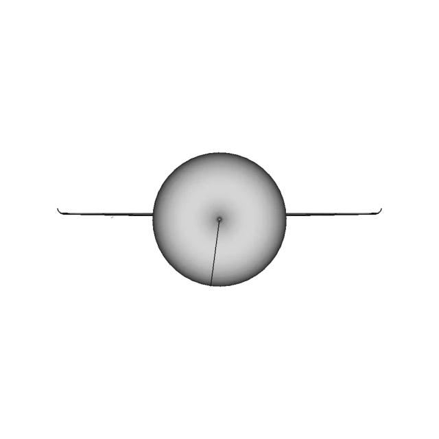
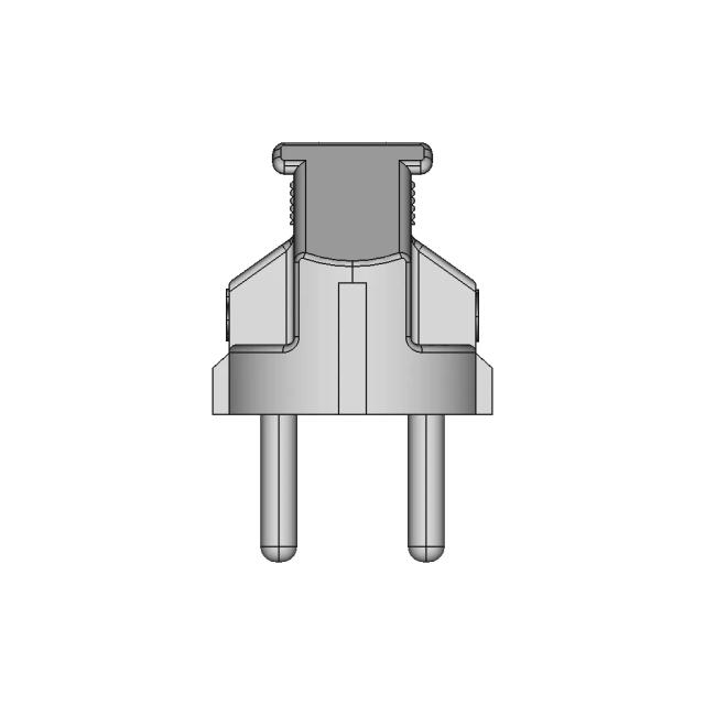
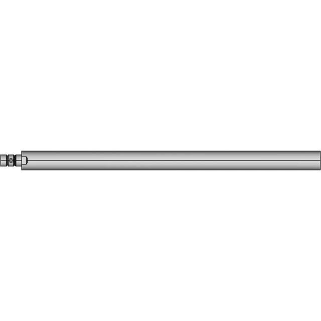
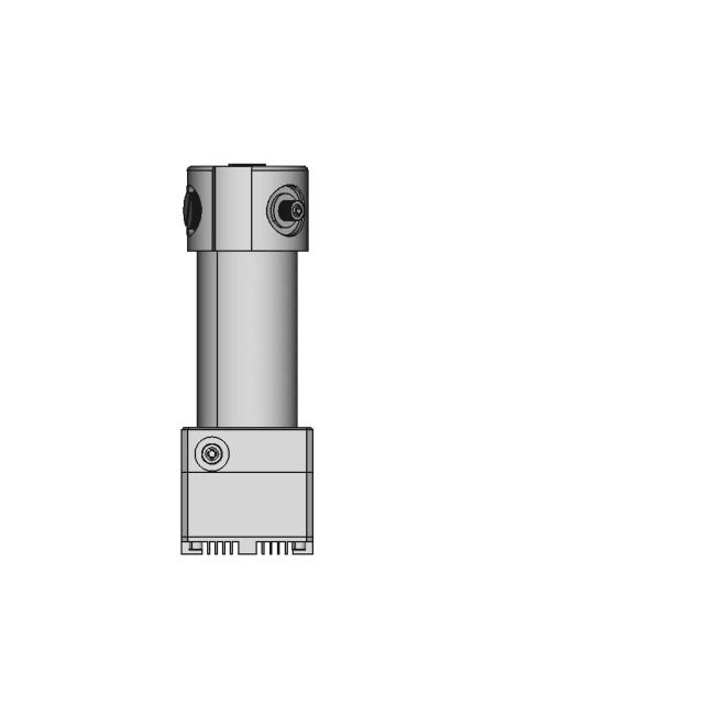
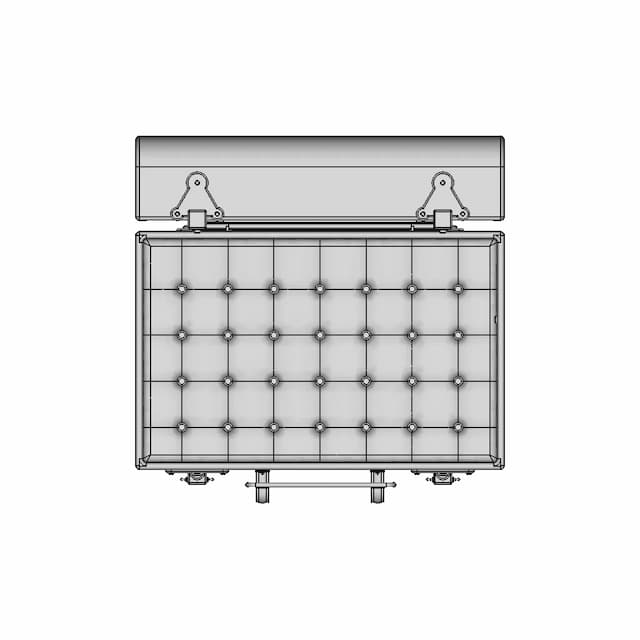
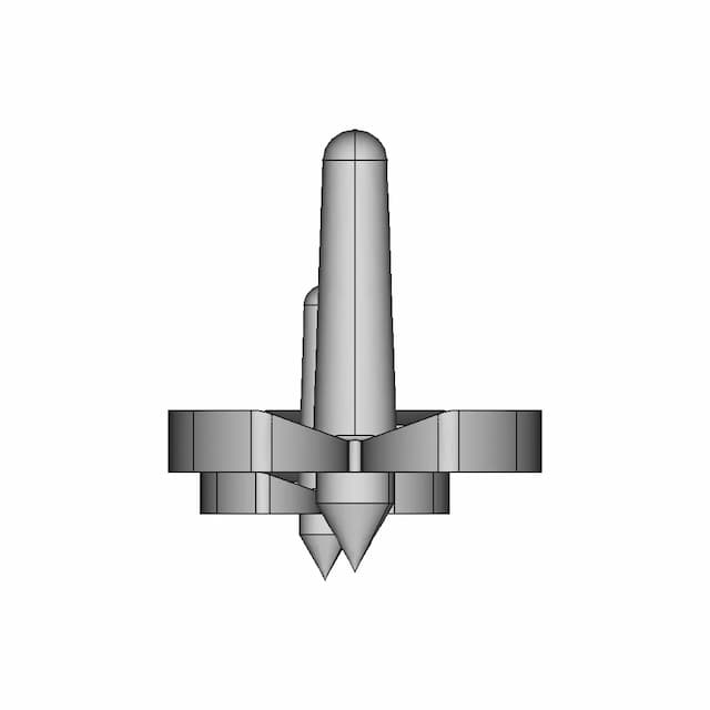
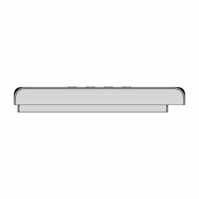
Standard conversions from live pricingLive pricingSTEP or STP to 2D drawings2D drawingsSee conversion pricingPricing
Marathon Logo
Why us?Dashboard
Library
Hire Designers
Tools
Resources
  1. Home /
  2. Library /
  3. 2D Technical Drawings /
  4. Generic Mechanical Component with Approximate Dimensions
📐 2D Technical Drawings🤖 AI Generated

Generic Mechanical Component with Approximate Dimensions 2D Technical Drawing Set

5
Drawing sheets
5
Views analysed
3
Export formats
1
Section cuts
1st Angle
Projection type
27 Sept 2026
Generated date
STEP
Source CAD format
Generic Mechanical Component with Approximate Dimensions
Source 3D model
MPreview · 2D Drawing Sheets
1 / 5
⚠Verify critical dimensions against the source CAD model before using these drawings for manufacturing or production release. Download the FCStd file where available for the most accurate editable source.
Sheet 1
Sheet 1
Download all drawing sheets
SVG5 files
DXF5 files
🧊Open source 3D CAD model→
ℹ️

These are 2D engineering drawings derived from the 3D CAD geometry. Verify critical dimensions against the source model before manufacturing.

🤖

Views, section cuts, and detail areas were selected by AI based on analysis of 6 rendered views of the 3D model.

AI Drawing Analysis

What the AI Decided & Why

The cards below explain how the generated drawing outputs and assets connect to the final technical sheets.

Sheet 1

Orthographic

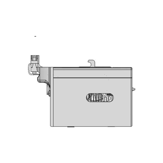
This sheet includes 102 geometry edges from the CAD projection pipeline.

Sheet 2

Orthographic

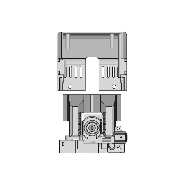
This sheet includes 50 geometry edges from the CAD projection pipeline.

Sheet 4

Orthographic

This sheet includes 111 geometry edges from the CAD projection pipeline.

Sheet 5

Orthographic

This sheet includes 50 geometry edges from the CAD projection pipeline.

Sheet 6

Orthographic

This sheet includes 106 geometry edges from the CAD projection pipeline.

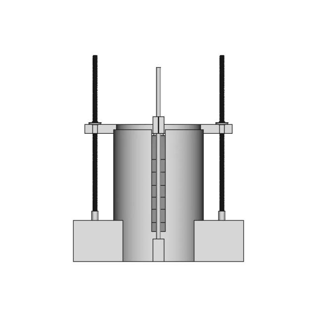
Sheet 4section_a · Section4
sheet_num: 4 · edges: 111

Sheet 4. Geometry is derived from the 3D model projection for this drawing set.

  • 111 resolved edges in sheet geometry
  • See technical_drawing_simple.pdf, sheet_N.pdf, and svg/ for full graphical context
  • Verify critical dimensions against the source CAD before manufacturing
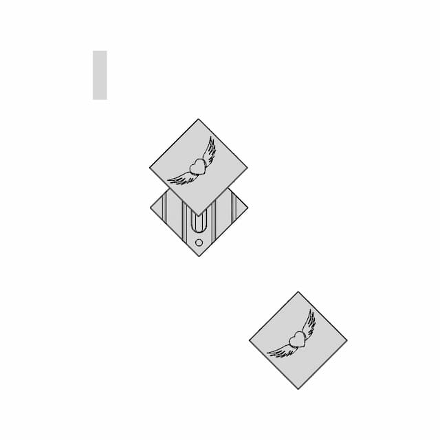
Detail Bdetail_b · base_view: Right
anchor: (30, 50, 0) · radius: 15

Magnifies the embossed 'TOYOTA' logo to ensure clarity of the branding and part identification.

  • Detail-view anchor selected by the AI planning stage
  • Use with sheet PDF/SVG for local feature inspection
  • Validate critical dimensions against source CAD before release

Downloads

Download Individual Sheets

Each sheet available in PDF, SVG, and DXF. Click a format badge to download.

Sheet 1
Sheet 2
Sheet 4
Sheet 5
Sheet 6

Drawing report

Drawing details & review

Cover summary and review report for this versioned drawing set.

TECHNICAL DRAWING

6983418a96888fd1a671ed85

Engine Valve Cover

5
sheets
5
control frames
4
dimensions not drawn
Sheet index
SheetViewScaleContent
1Assembly - Front View1.0standard_view
2Assembly - Right View1.0standard_view
3Assembly - Isometric View1.0standard_view
4Section A-A1.0section_view
5Detail B2.0detail_view

Generated automatically and intended for review before use. A companion review report lists what needs checking.

DRAWING REVIEW REPORT

6983418a96888fd1a671ed85

This drawing is generated automatically and is a first draft. The items below need a human decision.

Summary
24
dimensions drawn
4
selected, not drawn
5
control frames
3
assumed tolerances
Tolerances to verify
CharacteristicTolDatumsConfidenceReason
position1.5A | Cmediumbolt/hole pattern × 4 (position)
position1.0A | Cmediumbolt/hole pattern × 10 (position)
profile_of_a_surface0.6A | Cmedium556 face(s) have no analytic form — profile is the only control that applies to a sculpted surface
Dimensions not drawn
SheetTypeValueDescriptionReason
1Angle85.02x angle 85.0 degoverlaps prior label (tried 9 position(s))
6Diameter46.0Ø46.0mmoutside page band (tried 20 position(s))
6Diameter50.0Ø50.0mmDiameter ref Edge657 is Line; no nearby Circle/Arc (a substitute further away is another hole)
6Diameter60.0Ø60.0mmoutside page band (tried 20 position(s))
Tolerance schedule
CharacteristicTolZoneDatumsConfidence
flatness0.05high
perpendicularity0.2Ahigh
position1.5diameterA | Cmedium
position1.0diameterA | Cmedium
profile_of_a_surface0.6A | Cmedium
Dimension schedule

All 24 dimension(s) drawn.

#SheetTypeValueDescription
11DistanceX96.0overall width 96.0mm
21DistanceY591.4overall height 591.4mm
31Radius2.5R2.5mm
41Radius3.02x R3.0mm
51Radius5.02x R5.0mm
61Radius7.04x R7.0mm
71Radius15.0R15.0mm
82DistanceX230.0overall width 230.0mm
92DistanceY591.4overall height 591.4mm
102Radius44.03x R44.0mm
112Angle53.22x angle 53.2 deg
122DistanceY326.5hole pitch 326.5mm (2 x Ø30, from model)
132DistanceX134.9hole pattern width 134.9mm (4 x Ø21, from model)
142DistanceX155.6hole pitch 155.6mm (2 x Ø11.5, from model)
154DistanceX230.0overall width 230.0mm
164DistanceY591.4overall height 591.4mm
174Radius30.0R30.0mm
184Angle53.26x angle 53.2 deg
194DistanceY326.5hole pitch 326.5mm (2 x Ø30, from model)
204DistanceX134.9hole pattern width 134.9mm (4 x Ø21, from model)
214DistanceX155.6hole pitch 155.6mm (2 x Ø11.5, from model)
225Radius15.03x R15.0mm
236Radius1.02x R1.0mm
246Angle47.300000000000018x angle 47.3 deg

Paid Pipeline · $5.99 per drawing set

Have your own 3D CAD file?

Upload a STEP or STP file and generate a 2D drawing set with PDF, SVG and DXF outputs.

  • ✓ Usually ready in minutes
  • ✓ 9 sheets · editable FCStd + PDF, SVG, DXF
  • ✓ No subscription · pay per file
$5.99
per drawing set incl. GST
4 min
avg. turnaround

AI Transparency

How these drawings were generated

These drawings were generated from the source 3D CAD geometry. The system analysed the model, selected relevant views, planned section cuts and generated drawing sheets in PDF, SVG and DXF formats.

These are 2D engineering drawings, not 3D files. Dimensions are extracted from the 3D geometry and should be verified against the source model before use in manufacturing.

Run Metadata

5
Views analysed
5
Sheets generated
1
Section cuts
2
Export formats
27 Sept 2026
Generated date

Explore Marathon OS

Related resources

Jump to the source 3D model, generate your own drawings, or browse tools and libraries.

Open source 3D CAD modelPreview the original 3D geometry used to generate these drawings→
Generate your own 2D drawingUpload STEP, STP, IGES or FreeCAD — get PDF, SVG and DXF→Browse more 2D technical drawingsExplore AI-generated orthographic sheets across part types→Browse 3D CAD modelsDownload and preview open-source STEP, STL and IGES files→Open CAD files onlineView STEP, IGES, STL and more in your browser→Convert CAD files onlineConvert between STEP, STL, OBJ and other 3D formats→Get manual drafting supportWork with vetted CAD designers for production-ready drawings→

Preview the Source 3D CAD Model

Open the original 3D CAD model used to generate this 2D drawing set. Review the source geometry before downloading or using the technical drawings.

Open 3D CAD model →
Marathon Logo

The specialist CAD conversion platform for engineering, mesh and drawing workflows.

Start a conversion
ConvertAll 60+ conversion toolsSTEP to STLSTL to STEPIGES to STEPDWG to DXFSTEP or STP to 2D
Products3D CAD Products2D CAD Products
Tools and servicesAll CAD Tools3D CAD ViewerSTEP BOM ExtractorHire a CAD Designer
CompanyHomeAbout UsContact Us
LegalPrivacy PolicyTerms and ConditionsRefund Policy
© 2026 Marathon OS. All rights reserved.Convert precisely. Download confidently. Keep moving.

Recently added / Trending

Everything you need to design faster, smarter, and with more impact.

Cnc Learning 9 | High-Quality CAD Model
Scania B8X4Nb R660 Cab - Standard Mechanical Component
C14 Panel Mount With Fuse And Button 1 | 3D CAD Engineering Model
Piston Head For Compressor 1 | 3D CAD Engineering Model
Offshore Transmitter Site 1 | 3D CAD Engineering Model
Accurate HGX-Lite Extruder Model Based on Precise Measurements
Heusinkveld Sim Shifter Sequential
Propane Tank 100Lbs 1 | 3D CAD Engineering Model
Conveyor Sensor Adjustment Tool
Cable Holder | High-Quality CAD Model
View all designs

Marathon-OS Design Hub

Everything you need to design faster, smarter, and with more impact.

Freecad 099 | 3D Engineering Design File
CH-E3Dv6-Bowden Toolhead with E3Dv6 Hotend and BLTouch Sensor
Hoverboard Motor Holder 1 | 3D CAD Engineering Model
Secret Box V2 | 3D Engineering Design File
Older Version Covr3D V2 03 Fdm 3D Print Optimised Mask | Professional CAD Design
1.5 Meter Span Structural Component for 3D Printing
Balloon Dog 3 | 3D CAD Engineering Model
Kaffeefilterhalter 1 | 3D CAD Engineering Model
Rubber Tire Insert RC 1 for 3D Printing with TPU Material
Filament Spool Holder 16 | 3D CAD Engineering Model
3D Printed Vase 4 | Industrial CAD Design
Fissure V1 Step 1 | 3D CAD Engineering Model
Creality Watercooling Kit for Sprite Pro Extruder
Tufted Box | 3D Engineering Design File
3D Printed Spinner Toy | Unique Fidget Design ✨ - Downloadable CAD Representation
3D Printed Plastic Enclosure Case - Downloadable CAD Representation
View all designs

Explore More 2D Designs

View all
BIO REACTOR, Used for CFD Analysis for Projects
2D Drawing$5.99
M12 X-CODE CAT6A Plug - High-Performance Industrial Connector
2D Drawing$5.99
M12 X-Code Connector - High-Performance Industrial Connector
2D Drawing$5.99
Toyota Hilux Double Cab 3D CAD Model for Engineering and Design
2D Drawing$5.99
Offroad Transmission Undershield for Enhanced Protection
2D Drawing$5.99
Adjustable Square and Round Tube Rock Slider for Pickup Trucks
2D Drawing$5.99
Aluminum Off-Road Front Bumper for Toyota Hilux Vigo
2D Drawing$5.99
Toyota Hilux Revo Offroad Bumper 4x4 Concept 3D Model
2D Drawing$5.99