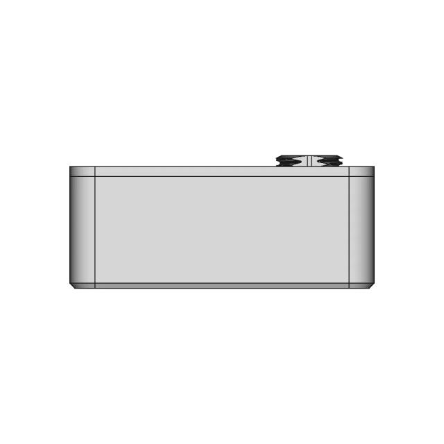
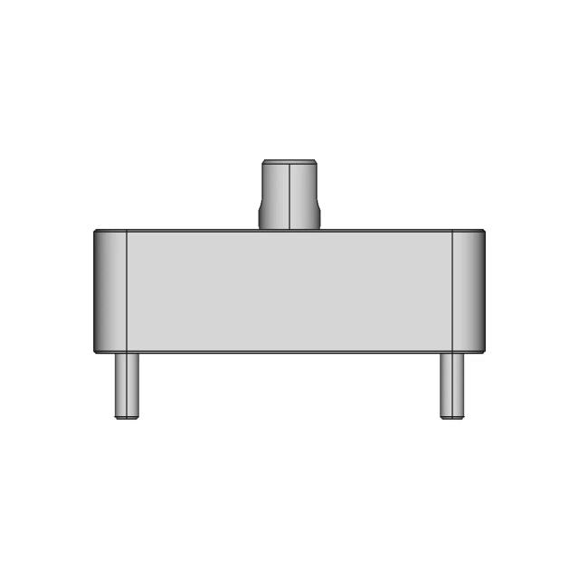
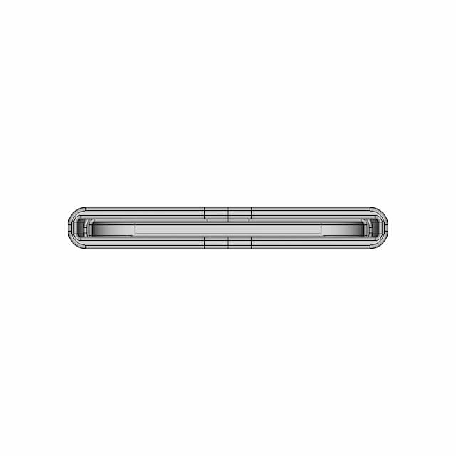
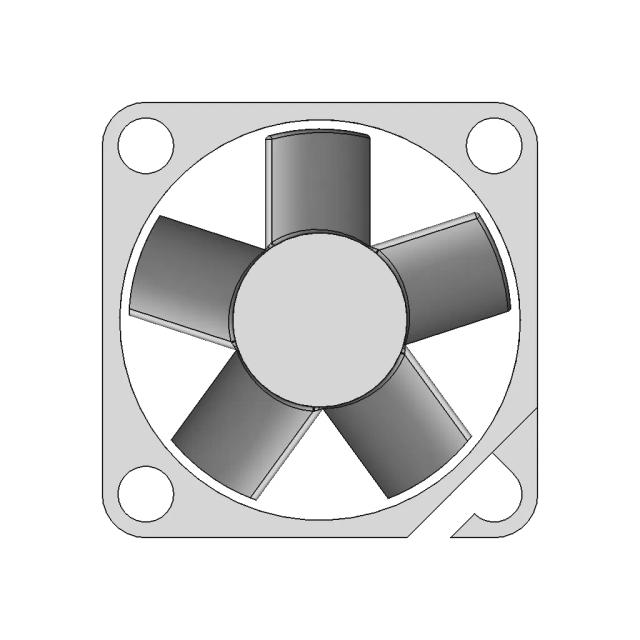
Standard conversions from live pricingLive pricingSTEP or STP to 2D drawings2D drawingsSee conversion pricingPricing
Marathon Logo
Why us?Dashboard
Library
Hire Designers
Tools
Resources
  1. Home /
  2. Library /
  3. 2D Technical Drawings /
  4. Hybrid Vertical Wind Turbine 2 | CAD Model for Energy Systems
📐 2D Technical Drawings🤖 AI Generated

Hybrid Vertical Wind Turbine 2 | CAD Model for Energy Systems 2D Technical Drawing Set

5
Drawing sheets
5
Views analysed
3
Export formats
2
Section cuts
1st Angle
Projection type
27 Jun 2026
Generated date
STEP
Source CAD format
Hybrid Vertical Wind Turbine 2 | CAD Model for Energy Systems
Source 3D model
MPreview · 2D Drawing Sheets
1 / 5
⚠Verify critical dimensions against the source CAD model before using these drawings for manufacturing or production release. Download the FCStd file where available for the most accurate editable source.
Assembly - Front View
Download all drawing sheets
PDF5 sheets
SVG5 files
DXF5 files
🧊Open source 3D CAD model→
ℹ️

These are 2D engineering drawings derived from the 3D CAD geometry. Verify critical dimensions against the source model before manufacturing.

🤖

Views, section cuts, and detail areas were selected by AI based on analysis of 6 rendered views of the 3D model.

AI Drawing Analysis

What the AI Decided & Why

The cards below explain how the generated drawing outputs and assets connect to the final technical sheets.

Assembly - Front View

Orthographic

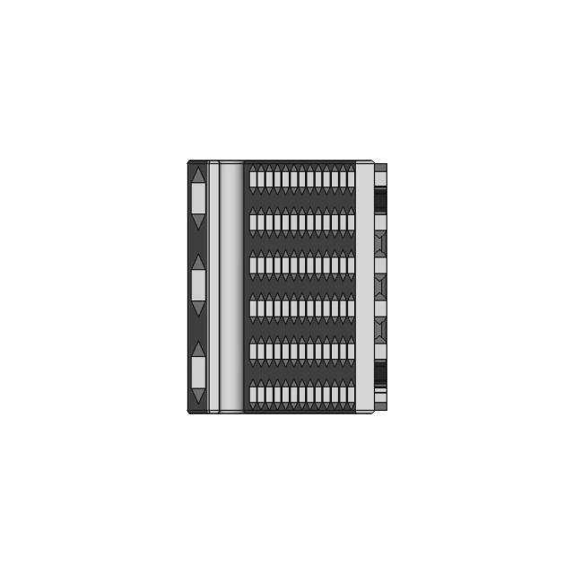
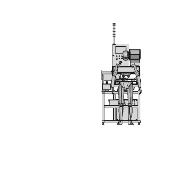
The Front view provides the primary orthographic projection, clearly showing the overall height, the central turbine hub, and the symmetrical arrangement of the blades and support structure. It is essential for understanding the main components and their vertical alignment.

Assembly - Top View

Orthographic

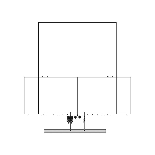
The Top view is critical for illustrating the horizontal layout of the turbine's rotor blades and the circular base of the tower. It reveals the bolt patterns and the radial symmetry of the assembly, which are key for manufacturing and installation.

Assembly - Left View

Orthographic

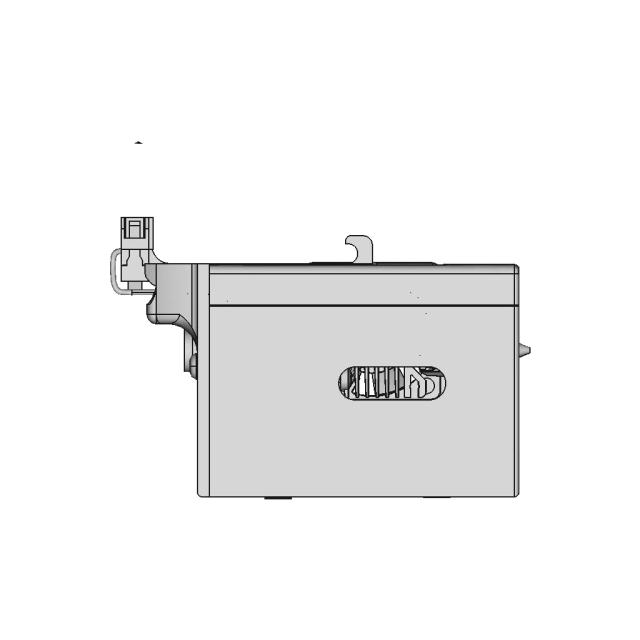
The Left view is included to show the side profile of the tower and the attachment points for the blades and control unit. It provides a unique perspective on the structural depth and the arrangement of the diagonal bracing.

Section A-A

Orthographic

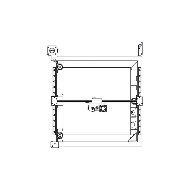
This section cut through the central tower reveals the internal flange structure, bolt patterns, and wall thicknesses of the tower's main column. It is necessary to show the internal construction details that are not visible in the external views.

Section B-B

Orthographic

This horizontal section cut through the turbine hub and blades shows the internal bore diameters, the alignment of the shafts, and the connection points for the blades to the central hub. It is essential for understanding the mechanical assembly of the turbine.

A — Asection_a · Section5
sheet_num: 5 · edges: 50

This section cut through the central tower reveals the internal flange structure, bolt patterns, and wall thicknesses of the tower's main column. It is necessary to show the internal construction details that are not visible in the external views.

  • 50 resolved edges in sheet geometry
  • See technical_drawing_simple.pdf, sheet_N.pdf, and svg/ for full graphical context
  • Verify critical dimensions against the source CAD before manufacturing
B — Bsection_b · Section6
sheet_num: 6 · edges: 50

This horizontal section cut through the turbine hub and blades shows the internal bore diameters, the alignment of the shafts, and the connection points for the blades to the central hub. It is essential for understanding the mechanical assembly of the turbine.

  • 50 resolved edges in sheet geometry
  • See technical_drawing_simple.pdf, sheet_N.pdf, and svg/ for full graphical context
  • Verify critical dimensions against the source CAD before manufacturing
Detail Cdetail_c · base_view: Front
anchor: (0, 0, 0) · radius: 10

This detail view magnifies the connection point between the blades and the central hub, highlighting the bolt pattern, the bore diameter, and the fillet radius. It is necessary to clearly show the small, critical features of the blade attachment.

  • Detail-view anchor selected by the AI planning stage
  • Use with sheet PDF/SVG for local feature inspection
  • Validate critical dimensions against source CAD before release
Detail Ddetail_d · base_view: Top
anchor: (0, 0, 0) · radius: 20

This detail view focuses on the base of the tower, showing the circular flange, the bolt pattern for the foundation, and the wall thickness. It is necessary to provide clear dimensions for the critical foundation connection.

  • Detail-view anchor selected by the AI planning stage
  • Use with sheet PDF/SVG for local feature inspection
  • Validate critical dimensions against source CAD before release

Downloads

Download Individual Sheets

Each sheet available in PDF, SVG, and DXF. Click a format badge to download.

Assembly - Front View
Assembly - Top View
Assembly - Left View
Section A-A
Section B-B

Paid Pipeline · $5.99 per drawing set

Have your own 3D CAD file?

Upload a STEP or STP file and generate a 2D drawing set with PDF, SVG and DXF outputs.

  • ✓ Usually ready in minutes
  • ✓ 9 sheets · editable FCStd + PDF, SVG, DXF
  • ✓ No subscription · pay per file
$5.99
per drawing set incl. GST
4 min
avg. turnaround

AI Transparency

How these drawings were generated

These drawings were generated from the source 3D CAD geometry. The system analysed the model, selected relevant views, planned section cuts and generated drawing sheets in PDF, SVG and DXF formats.

These are 2D engineering drawings, not 3D files. Dimensions are extracted from the 3D geometry and should be verified against the source model before use in manufacturing.

Run Metadata

5
Views analysed
5
Sheets generated
2
Section cuts
3
Export formats
27 Jun 2026
Generated date

Explore Marathon OS

Related resources

Jump to the source 3D model, generate your own drawings, or browse tools and libraries.

Open source 3D CAD modelPreview the original 3D geometry used to generate these drawings→
Generate your own 2D drawingUpload STEP, STP, IGES or FreeCAD — get PDF, SVG and DXF→Browse more 2D technical drawingsExplore AI-generated orthographic sheets across part types→Browse 3D CAD modelsDownload and preview open-source STEP, STL and IGES files→Open CAD files onlineView STEP, IGES, STL and more in your browser→Convert CAD files onlineConvert between STEP, STL, OBJ and other 3D formats→Get manual drafting supportWork with vetted CAD designers for production-ready drawings→

Preview the Source 3D CAD Model

Open the original 3D CAD model used to generate this 2D drawing set. Review the source geometry before downloading or using the technical drawings.

Open 3D CAD model →
Marathon Logo

The specialist CAD conversion platform for engineering, mesh and drawing workflows.

Start a conversion
ConvertAll 60+ conversion toolsSTEP to STLSTL to STEPIGES to STEPDWG to DXFSTEP or STP to 2D
Products3D CAD Products2D CAD Products
Tools and servicesAll CAD Tools3D CAD ViewerSTEP BOM ExtractorHire a CAD Designer
CompanyHomeAbout UsContact Us
LegalPrivacy PolicyTerms and ConditionsRefund Policy
© 2026 Marathon OS. All rights reserved.Convert precisely. Download confidently. Keep moving.

Recently added / Trending

Everything you need to design faster, smarter, and with more impact.

Water Pressure Gauge for Reverse Osmosis Filtration Systems
RS Pro 177 4516 Linear Actuator
Cube Cube
Cube Cube
Honda IGXV700 800 Engine with Canister
Vtx 215 003 Xxx 1 | CAD Model for Energy Systems
Green Lezard Perfume 1 | Professional CAD Design
Spur Gear Speed Reducer Gearbox - Standard Mechanical Component
Practice - Downloadable CAD Representation
Mechanical Iris | High-Quality CAD Model
Marine Propeller Model Kp505 - Downloadable CAD Representation
View all designs

Marathon-OS Design Hub

Everything you need to design faster, smarter, and with more impact.

Vent 16 Mm 1 | 3D CAD Engineering Model
Compact Mini Case with GX12 Connector for 3D Printing
One Of Seven | 3D CAD Engineering Model
Morbius Strip 2 | 3D CAD Engineering Model
Protection Cap Tcf254.254 (Moldable) | 3D Engineering Design File
Ledger Logo 1 | 3D CAD Engineering Model
Sunon MagLev Brushless DC Motor Fan MF25100V1-1000U-A99
Apple TV Siri Remote Holder - Secure and Convenient Storage
BIO REACTOR, Used for CFD Analysis for Projects
Gopro Mask Mount 1 | 3D CAD Engineering Model
CH-E3Dv6-Bowden Toolhead with E3Dv6 Hotend and BLTouch Sensor
Dragon 3D Printer
Dragon 3D Printer
Nutcracker - Nussknacker | 3D Engineering Design File
Orange 6 | 3D CAD Engineering Model
Traditional Indian Bow | Scalable Resin 3D Print Model | 3D Engineering Design File
Universal Rod Holder 1 | 3D CAD Engineering Model
View all designs

Explore More 2D Designs

View all
BIO REACTOR, Used for CFD Analysis for Projects
2D Drawing$5.99
M12 X-CODE CAT6A Plug - High-Performance Industrial Connector
2D Drawing$5.99
M12 X-Code Connector - High-Performance Industrial Connector
2D Drawing$5.99
Toyota Hilux Double Cab 3D CAD Model for Engineering and Design
2D Drawing$5.99
Offroad Transmission Undershield for Enhanced Protection
2D Drawing$5.99
Adjustable Square and Round Tube Rock Slider for Pickup Trucks
2D Drawing$5.99
Aluminum Off-Road Front Bumper for Toyota Hilux Vigo
2D Drawing$5.99
Toyota Hilux Revo Offroad Bumper 4x4 Concept 3D Model
2D Drawing$5.99