Sheet 1
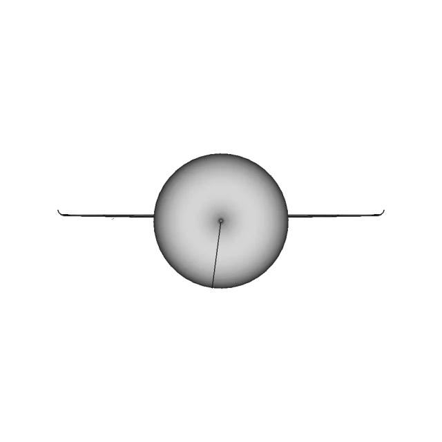
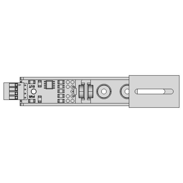
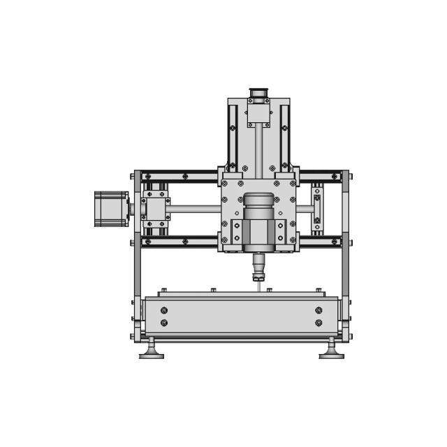
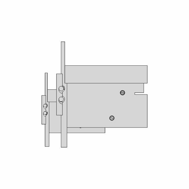
OrthographicThis sheet includes 86 geometry edges from the CAD projection pipeline.
AI Drawing Analysis
The cards below explain how the generated drawing outputs and assets connect to the final technical sheets.
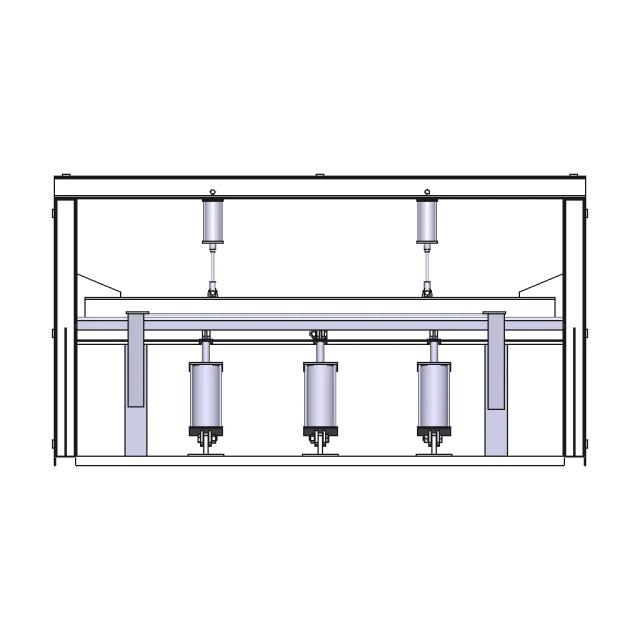
This sheet includes 86 geometry edges from the CAD projection pipeline.
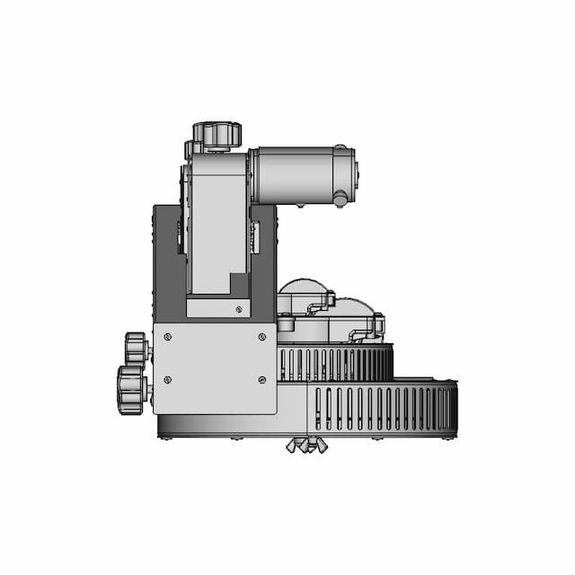
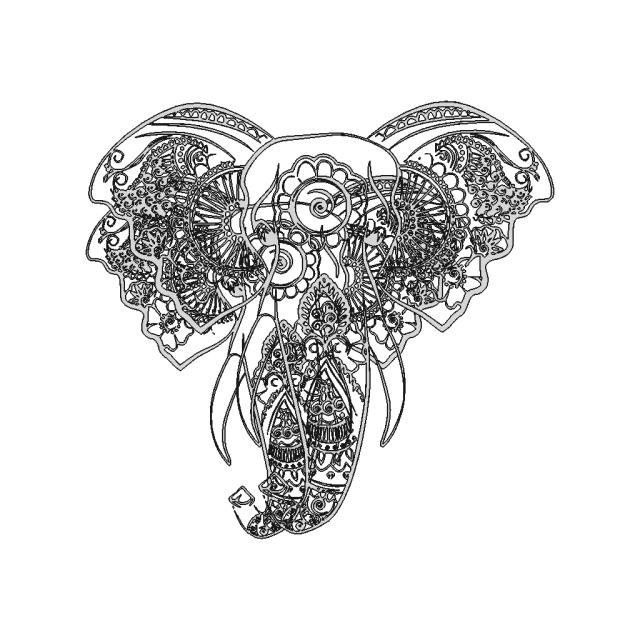
This sheet includes 93 geometry edges from the CAD projection pipeline.
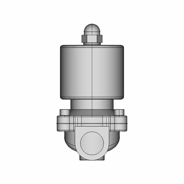
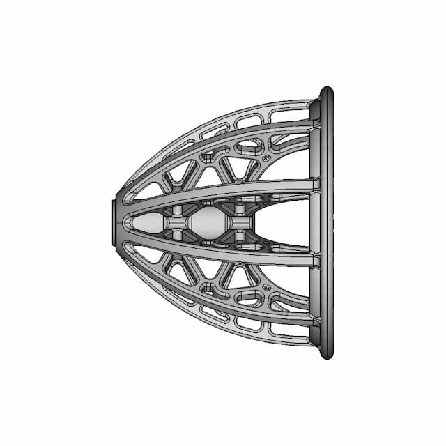
This sheet includes 97 geometry edges from the CAD projection pipeline.
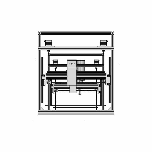
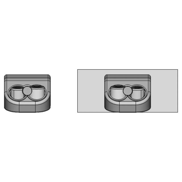
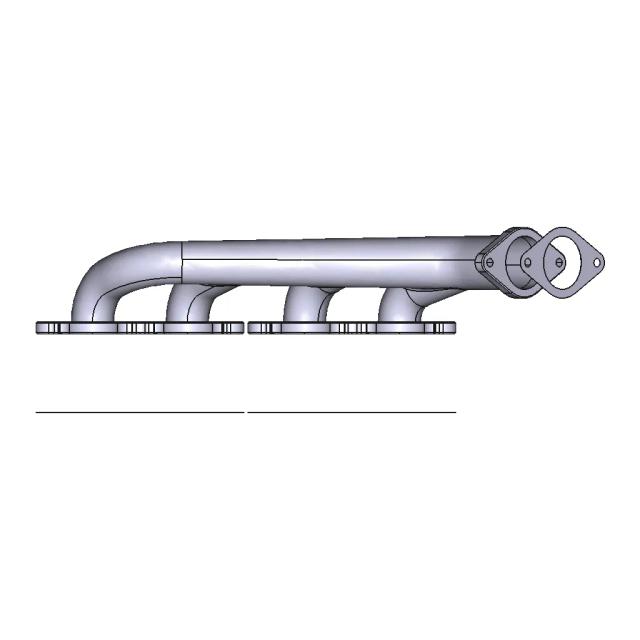
This sheet includes 89 geometry edges from the CAD projection pipeline.
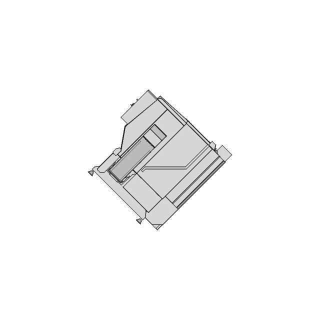
This sheet includes 86 geometry edges from the CAD projection pipeline.
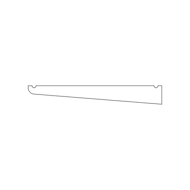
Sheet 5. Geometry is derived from the 3D model projection for this drawing set.
Magnifies the circular opening to show its exact dimensions and internal features.
Downloads
Each sheet available in PDF, SVG, and DXF. Click a format badge to download.
Drawing report
Cover summary and review report for this versioned drawing set.
Air Handling Unit
| Sheet | View | Scale | Content |
|---|---|---|---|
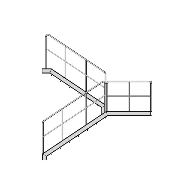
| 1 | Assembly - Front View | 0.2 | standard_view |
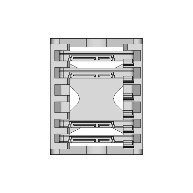
| 2 | Assembly - Top View | 0.25 | standard_view |
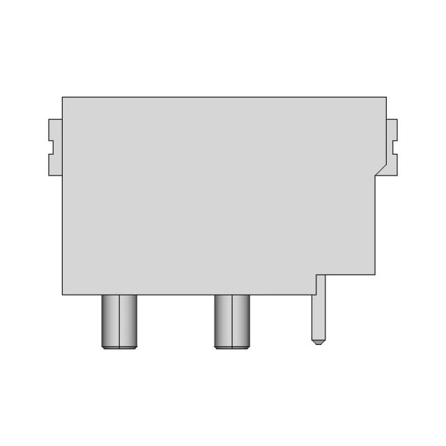
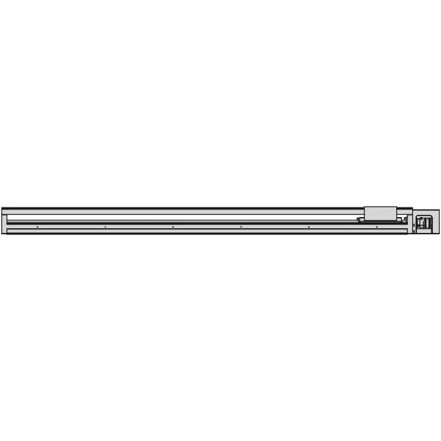
| 3 | Assembly - Left View | 0.2 | standard_view |
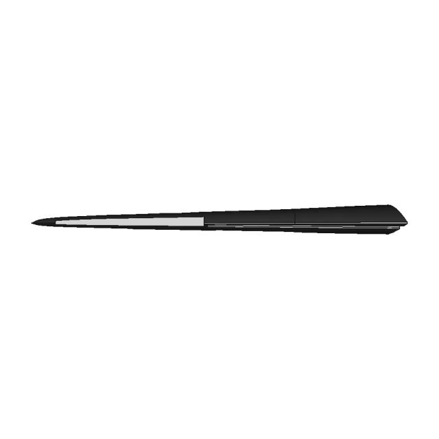
| 4 | Assembly - Isometric View | 0.2 | standard_view |
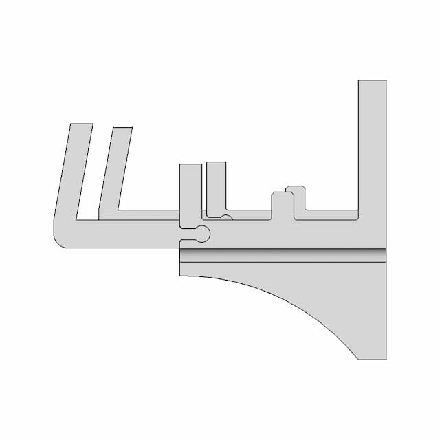
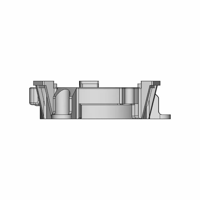
| 5 | Section A-A | 0.2 | section_view |
| 6 | Detail B | 2.0 | detail_view |
Generated automatically and intended for review before use. A companion review report lists what needs checking.
This drawing is generated automatically and is a first draft. The items below need a human decision.
| Characteristic | Tol | Datums | Confidence | Reason |
|---|---|---|---|---|
| position | 0.3 | B | C | A | low | bolt/hole pattern × 4 (position) |
| Characteristic | Tol | Zone | Datums | Confidence |
|---|---|---|---|---|
| flatness | 0.2 | high | ||
| perpendicularity | 0.3 | B | high | |
| position | 0.3 | diameter | B | C | A | low |
All 29 dimension(s) drawn.
| # | Sheet | Type | Value | Description |
|---|---|---|---|---|
| 1 | 1 | DistanceX | 2712.0 | overall width 2712.0mm |
| 2 | 1 | DistanceY | 2695.6 | overall height 2695.6mm |
| 3 | 1 | DistanceX | 2233.0 | width 2233.0mm at y≈-1098.36mm [unverified span] |
| 4 | 1 | DistanceX | 2070.0 | width 2070.0mm at y≈528.8399999999999mm [unverified span] |
| 5 | 2 | DistanceX | 2712.0 | overall width 2712.0mm |
| 6 | 2 | DistanceY | 1638.0 | overall height 1638.0mm |
| 7 | 2 | Diameter | 28.0 | 4x Ø28.0mm |
| 8 | 2 | Diameter | 32.0 | 4x Ø32.0mm |
| 9 | 2 | DistanceX | 332.0 | hole pitch 332.0mm (horizontal, Ø28) |
| 10 | 2 | Radius | 1.5 | 59x R1.5mm |
| 11 | 2 | Radius | 4.5 | 64x R4.5mm |
| 12 | 2 | Angle | 45.0 | 2x angle 45.0 deg |
| 13 | 3 | DistanceX | 1638.0 | overall width 1638.0mm |
| 14 | 3 | DistanceY | 2695.6 | overall height 2695.6mm |
| 15 | 3 | Diameter | 785.0 | Ø785.0mm |
| 16 | 3 | Diameter | 795.0 | Ø795.0mm |
| 17 | 3 | Radius | 1.5 | 18x R1.5mm |
| 18 | 3 | Radius | 4.5 | 20x R4.5mm |
| 19 | 3 | Radius | 100.0 | 2x R100.0mm |
| 20 | 3 | Angle | 45.1 | 10x angle 45.1 deg |
| 21 | 3 | DistanceY | 1101.0 | hole pitch 1101.0mm (2 x Ø32, from model) |
| 22 | 5 | DistanceX | 1638.0 | overall width 1638.0mm |
| 23 | 5 | Radius | 100.0 | R100.0mm |
| 24 | 5 | DistanceY | 1680.0 | height 1680.0mm at x≈-111.94019999999998mm [unverified span] |
| 25 | 5 | DistanceY | 1600.0 | height 1600.0mm at x≈-149.25359999999998mm [unverified span] |
| 26 | 5 | DistanceY | 1280.0 | height 1280.0mm at x≈-522.3875999999999mm [unverified span] |
| 27 | 5 | DistanceY | 1101.0 | hole pitch 1101.0mm (2 x Ø32, from model) |
| 28 | 6 | Radius | 1.5 | 9x R1.5mm |
| 29 | 6 | Radius | 4.5 | 11x R4.5mm |
AI Transparency
These drawings were generated from the source 3D CAD geometry. The system analysed the model, selected relevant views, planned section cuts and generated drawing sheets in PDF, SVG and DXF formats.
These are 2D engineering drawings, not 3D files. Dimensions are extracted from the 3D geometry and should be verified against the source model before use in manufacturing.
Run Metadata
Explore Marathon OS
Jump to the source 3D model, generate your own drawings, or browse tools and libraries.
Open the original 3D CAD model used to generate this 2D drawing set. Review the source geometry before downloading or using the technical drawings.
Open 3D CAD model →Everything you need to design faster, smarter, and with more impact.





Everything you need to design faster, smarter, and with more impact.