Standard conversions from live pricingLive pricingSTEP or STP to 2D drawings2D drawingsSee conversion pricingPricing
Marathon Logo
Why us?Dashboard
Library
Hire Designers
Tools
Resources
  1. Home /
  2. Library /
  3. 2D Technical Drawings /
  4. Pipe Inspection Robot - Standard Mechanical Component
📐 2D Technical Drawings🤖 AI Generated

Pipe Inspection Robot - Standard Mechanical Component 2D Technical Drawing Set

4
Drawing sheets
4
Views analysed
3
Export formats
1
Section cuts
1st Angle
Projection type
27 Jun 2026
Generated date
STEP
Source CAD format
Pipe Inspection Robot - Standard Mechanical Component
Source 3D model
MPreview · 2D Drawing Sheets
1 / 4
⚠Verify critical dimensions against the source CAD model before using these drawings for manufacturing or production release. Download the FCStd file where available for the most accurate editable source.
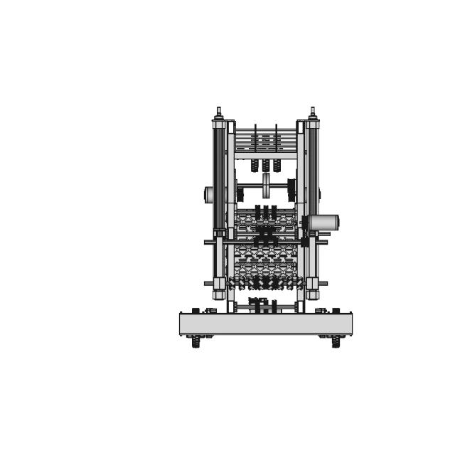
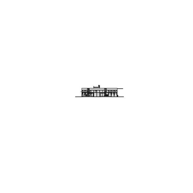
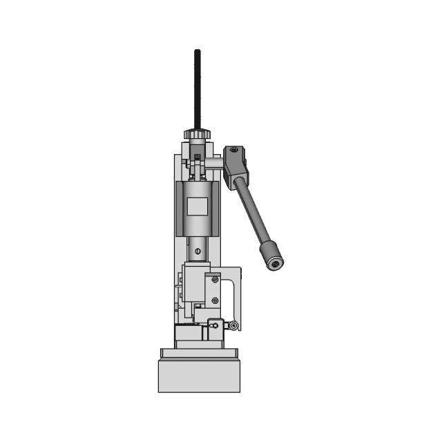
Assembly - Front View
Download all drawing sheets
PDF4 sheets
SVG4 files
DXF4 files
🧊Open source 3D CAD model→
ℹ️

These are 2D engineering drawings derived from the 3D CAD geometry. Verify critical dimensions against the source model before manufacturing.

🤖

Views, section cuts, and detail areas were selected by AI based on analysis of 6 rendered views of the 3D model.

AI Drawing Analysis

What the AI Decided & Why

The cards below explain how the generated drawing outputs and assets connect to the final technical sheets.

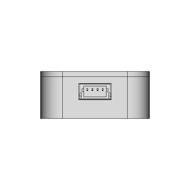
Assembly - Front View

Orthographic

Shows the full length, overall height, and key external features including the ribbed heat-dissipating housing, top and bottom drive shafts, and the central camera/processor module. Essential for establishing overall envelope and mounting interface.
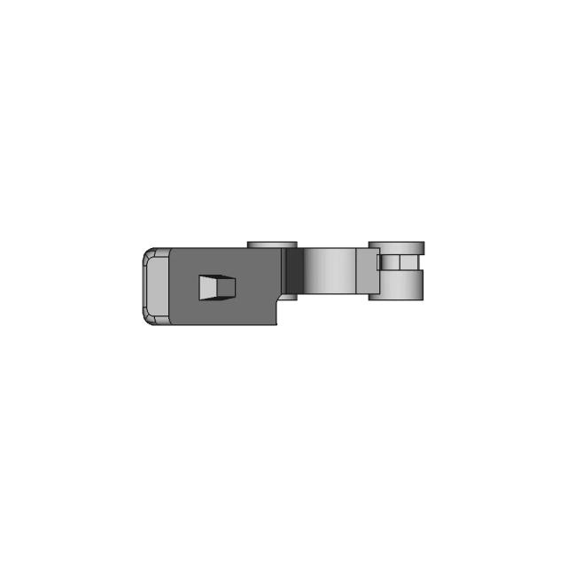
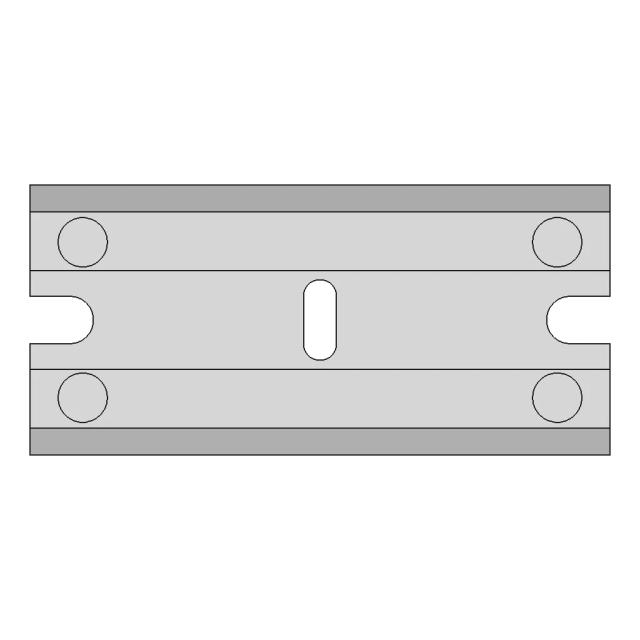
Assembly - Top View

Orthographic

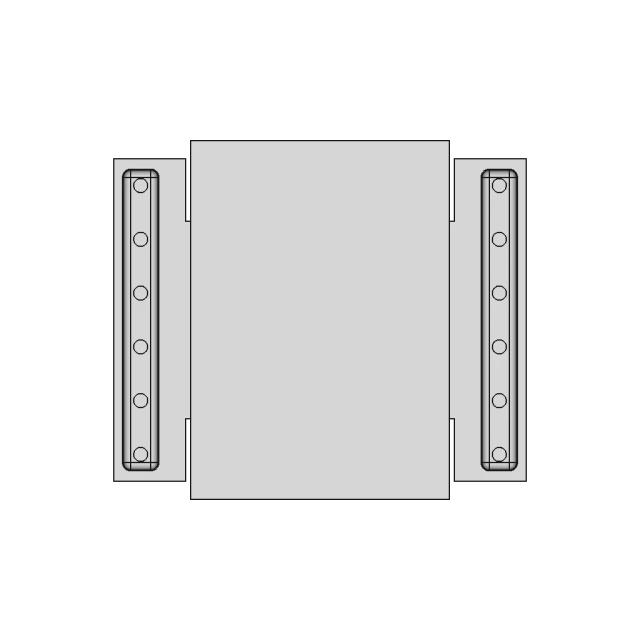
Reveals the dual-track layout, track width, bolt pattern for track mounting, and the spatial arrangement of the articulated linkage arms. Critical for understanding ground contact, stability, and track alignment.

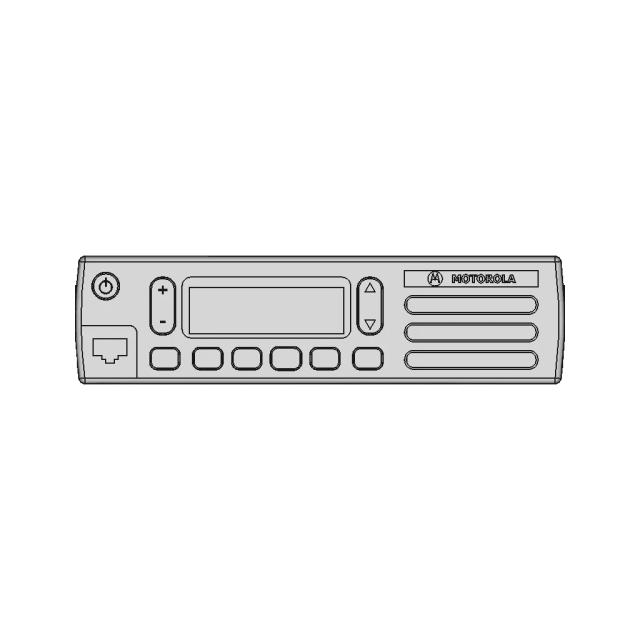
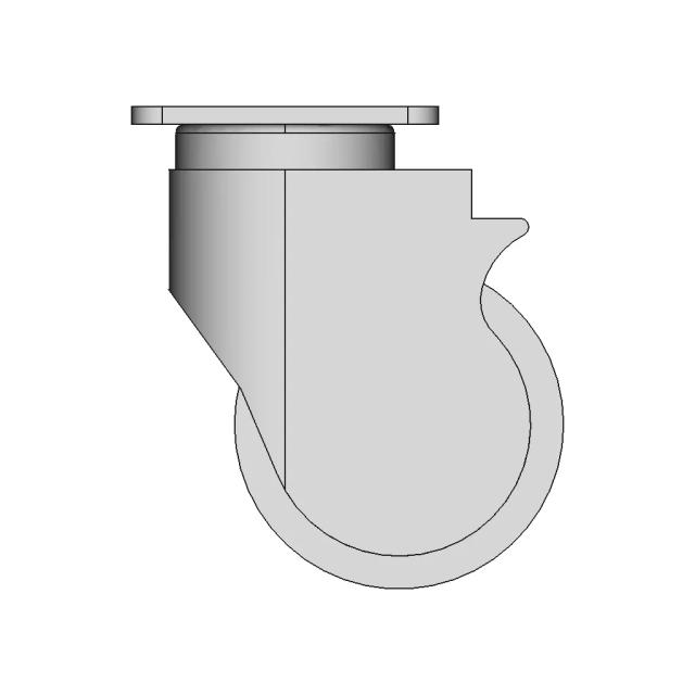
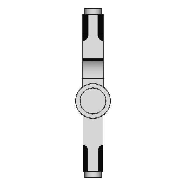
Assembly - Left View

Orthographic

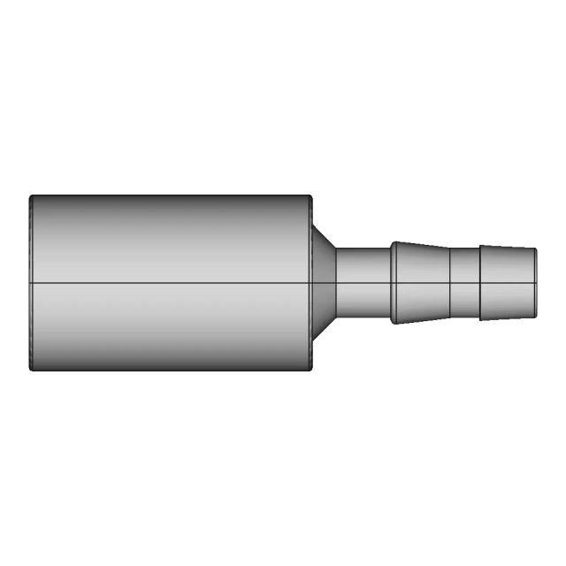
Shows the side profile, depth of the housing, and the internal layout of the drive shafts and mounting flanges. Highlights the symmetry and clearance between components, especially the central bore and side-mounted actuators.

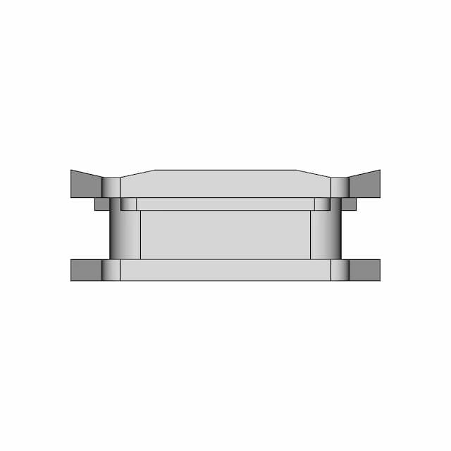
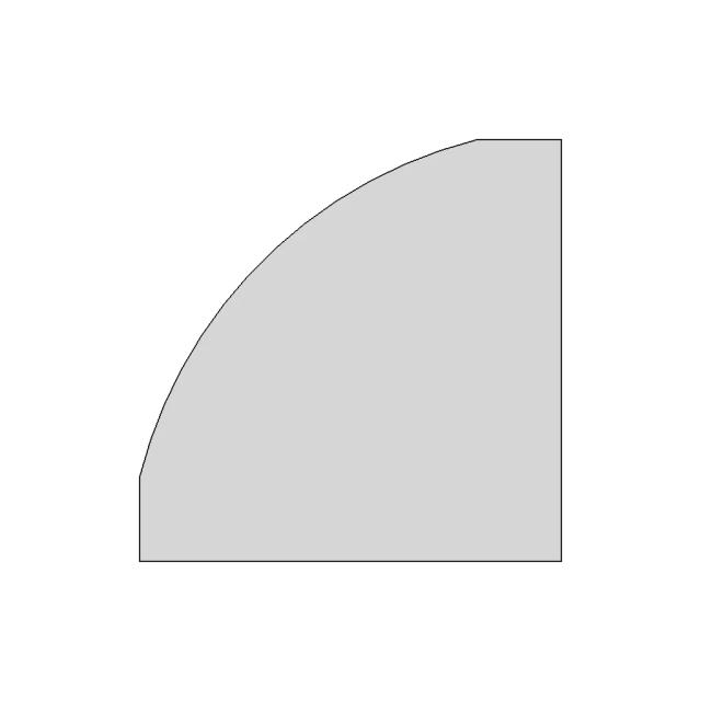
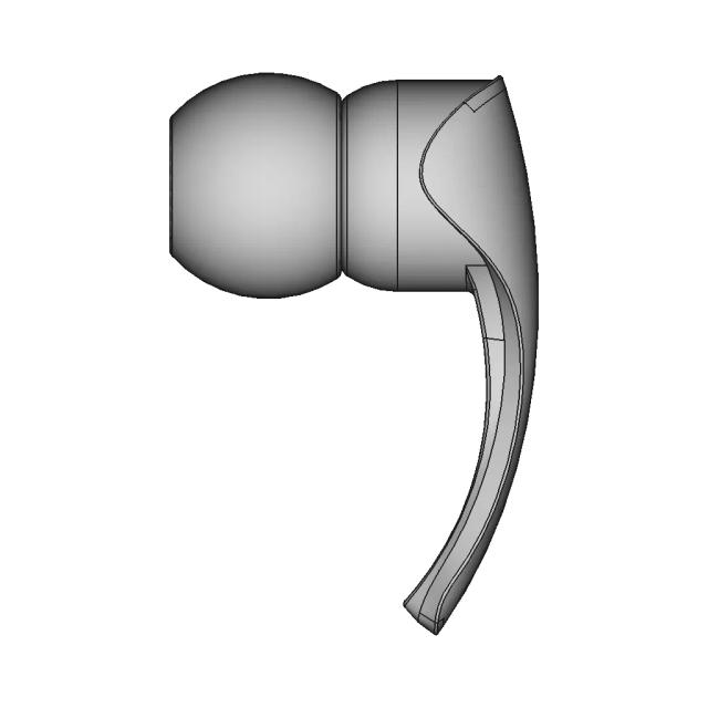
Section A-A

Orthographic

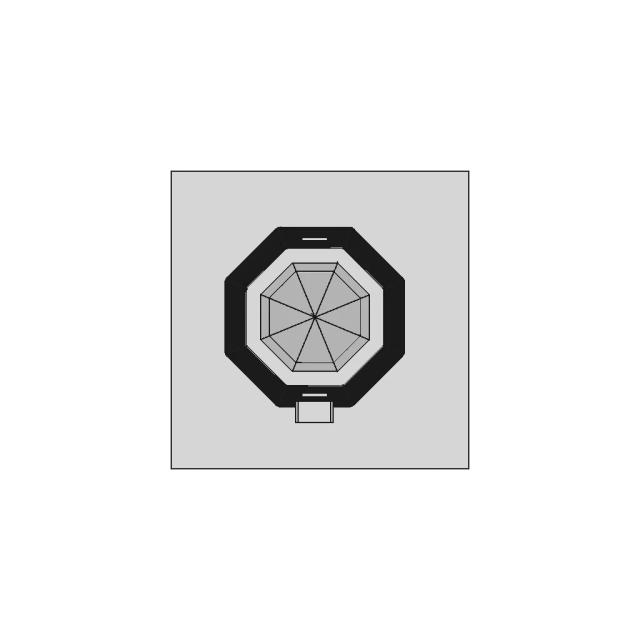
A horizontal section through the mid-plane (Z = 57.74 mm) reveals the internal bore of the central housing, the wall thickness of the ribbed casing, and the alignment of the drive shafts relative to the housing. Shows how the camera module is mounted and how the tracks interface with the central frame.

A — Asection_a · Section5
sheet_num: 5 · edges: 23

A horizontal section through the mid-plane (Z = 57.74 mm) reveals the internal bore of the central housing, the wall thickness of the ribbed casing, and the alignment of the drive shafts relative to the housing. Shows how the camera module is mounted and how the tracks interface with the central frame.

  • 23 resolved edges in sheet geometry
  • See technical_drawing_simple.pdf, sheet_N.pdf, and svg/ for full graphical context
  • Verify critical dimensions against the source CAD before manufacturing
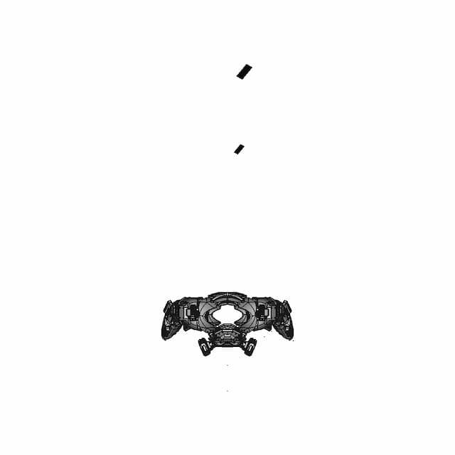
Detail Cdetail_c · base_view: Top
anchor: (0, 0, 0) · radius: 10

Magnifies the bolt hole pattern on the track mounting plate, showing the 4× M6 threaded holes arranged in a square (25 mm pitch) with a central alignment hole. Critical for ensuring proper track attachment and preventing misalignment during assembly.

  • Detail-view anchor selected by the AI planning stage
  • Use with sheet PDF/SVG for local feature inspection
  • Validate critical dimensions against source CAD before release

Downloads

Download Individual Sheets

Each sheet available in PDF, SVG, and DXF. Click a format badge to download.

Assembly - Front View
Assembly - Top View
Assembly - Left View
Section A-A

Paid Pipeline · $5.99 per drawing set

Have your own 3D CAD file?

Upload a STEP or STP file and generate a 2D drawing set with PDF, SVG and DXF outputs.

  • ✓ Usually ready in minutes
  • ✓ 9 sheets · editable FCStd + PDF, SVG, DXF
  • ✓ No subscription · pay per file
$5.99
per drawing set incl. GST
4 min
avg. turnaround

AI Transparency

How these drawings were generated

These drawings were generated from the source 3D CAD geometry. The system analysed the model, selected relevant views, planned section cuts and generated drawing sheets in PDF, SVG and DXF formats.

These are 2D engineering drawings, not 3D files. Dimensions are extracted from the 3D geometry and should be verified against the source model before use in manufacturing.

Run Metadata

4
Views analysed
4
Sheets generated
1
Section cuts
3
Export formats
27 Jun 2026
Generated date

Explore Marathon OS

Related resources

Jump to the source 3D model, generate your own drawings, or browse tools and libraries.

Open source 3D CAD modelPreview the original 3D geometry used to generate these drawings→
Generate your own 2D drawingUpload STEP, STP, IGES or FreeCAD — get PDF, SVG and DXF→Browse more 2D technical drawingsExplore AI-generated orthographic sheets across part types→Browse 3D CAD modelsDownload and preview open-source STEP, STL and IGES files→Open CAD files onlineView STEP, IGES, STL and more in your browser→Convert CAD files onlineConvert between STEP, STL, OBJ and other 3D formats→Get manual drafting supportWork with vetted CAD designers for production-ready drawings→

Preview the Source 3D CAD Model

Open the original 3D CAD model used to generate this 2D drawing set. Review the source geometry before downloading or using the technical drawings.

Open 3D CAD model →
Marathon Logo

The specialist CAD conversion platform for engineering, mesh and drawing workflows.

Start a conversion
ConvertAll 60+ conversion toolsSTEP to STLSTL to STEPIGES to STEPDWG to DXFSTEP or STP to 2D
Products3D CAD Products2D CAD Products
Tools and servicesAll CAD Tools3D CAD ViewerSTEP BOM ExtractorHire a CAD Designer
CompanyHomeAbout UsContact Us
LegalPrivacy PolicyTerms and ConditionsRefund Policy
© 2026 Marathon OS. All rights reserved.Convert precisely. Download confidently. Keep moving.

Recently added / Trending

Everything you need to design faster, smarter, and with more impact.

Classic Wheel and Axle Cart Assembly Model
Compact 3D Printable Mini Bot with Cargo Catapult Mechanism
Precision Mechanical Component for Industrial Applications
3D Printable Bioreactor For Deep Space Food Production | High-Quality CAD Model
Toy Turbine 1 | 3D CAD Engineering Model
Pnr5020 Smd Power Inductor | 3D Engineering Design File
Mechanical Design for Avionic Electronic System with Custom Battery and Integrated Components
Drone Soccer V2 1 | Professional CAD Design
Exhaust Silencer 3 | 3D CAD Engineering Model
Iae S.P.A. C30 Housing For C-Arm | 3D Engineering Design File
View all designs

Marathon-OS Design Hub

Everything you need to design faster, smarter, and with more impact.

Printable Armor | 3D Engineering Design File
IGES and STL File Formats for CAD Models
Eternal Crochet Flower Vase 1 | 3D CAD Engineering Model
Star 2500 1 | 3D CAD Engineering Model
Innovative Rolling Habitat Transport System for Lunar Surface
Sheath For Global Gs 38 9Cm 1 | 3D CAD Engineering Model
Maximum Bite Plant V2 1 | 3D CAD Engineering Model
3D Printable Bioreactor For Deep Space Food Production - Downloadable CAD Representation
Bass Sign 2 | 3D CAD Engineering Model
Corner Holder for 20x20 Sigma 3D Printer Frame
3D Printed Protective Case for Environmental Sensor
Enclosure For T Display S3 Amoled Microcomputer 1 | 3D CAD Engineering Model
Ratrig Vcore 3.1 Xy Joiner-Aluminum | 3D Engineering Design File
Support Mural Capteur De Mouvement Sonoff 1 | 3D CAD Engineering Model
Plastic Loop for 3D Printer Filament Loading
Anycubic Photon Mono 4 Drip Hanger 1 | Industrial CAD Design
View all designs

Explore More 2D Designs

View all
BIO REACTOR, Used for CFD Analysis for Projects
2D Drawing$5.99
M12 X-CODE CAT6A Plug - High-Performance Industrial Connector
2D Drawing$5.99
M12 X-Code Connector - High-Performance Industrial Connector
2D Drawing$5.99
Toyota Hilux Double Cab 3D CAD Model for Engineering and Design
2D Drawing$5.99
Offroad Transmission Undershield for Enhanced Protection
2D Drawing$5.99
Adjustable Square and Round Tube Rock Slider for Pickup Trucks
2D Drawing$5.99
Aluminum Off-Road Front Bumper for Toyota Hilux Vigo
2D Drawing$5.99
Toyota Hilux Revo Offroad Bumper 4x4 Concept 3D Model
2D Drawing$5.99