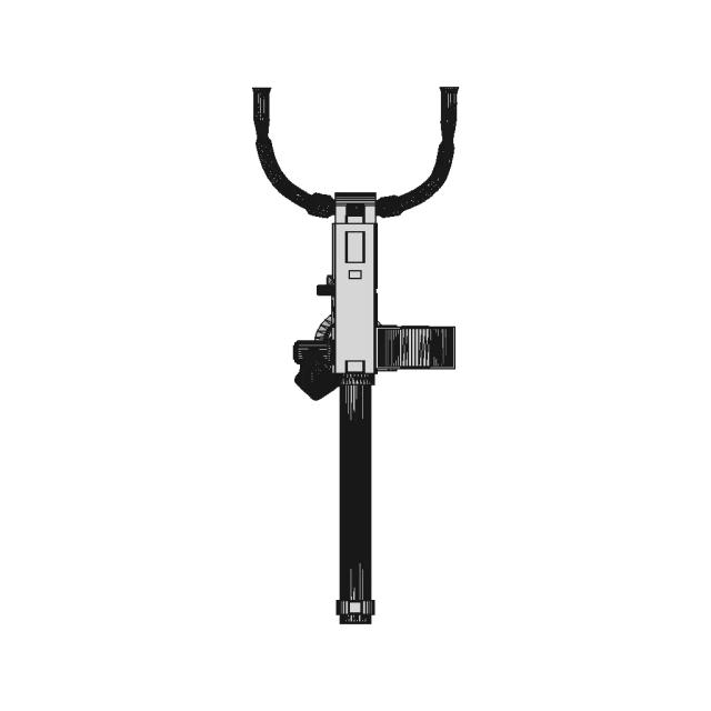
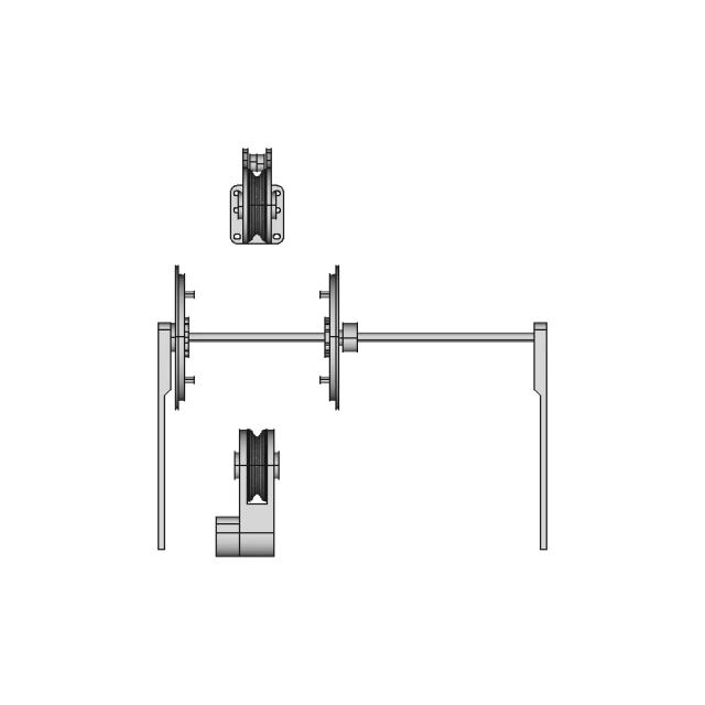
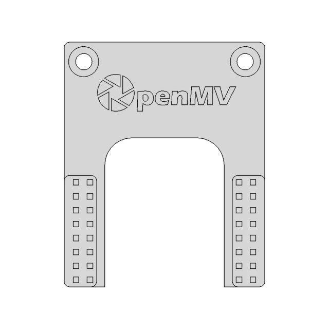
Standard conversions from live pricingLive pricingSTEP or STP to 2D drawings2D drawingsSee conversion pricingPricing
Marathon Logo
Why us?Dashboard
Library
Hire Designers
Tools
Resources
  1. Home /
  2. Library /
  3. 2D Technical Drawings /
  4. Professional Tilt Drawing Table for Precision Work
📐 2D Technical Drawings🤖 AI Generated

Professional Tilt Drawing Table for Precision Work 2D Technical Drawing Set

9
Drawing sheets
9
Views analysed
3
Export formats
2
Section cuts
1st Angle
Projection type
26 Sept 2026
Generated date
STEP
Source CAD format
Professional Tilt Drawing Table for Precision Work
Source 3D model
MPreview · 2D Drawing Sheets
1 / 9
⚠Verify critical dimensions against the source CAD model before using these drawings for manufacturing or production release. Download the FCStd file where available for the most accurate editable source.
Sheet 1
Sheet 1
Download all drawing sheets
SVG9 files
DXF9 files
🧊Open source 3D CAD model→
ℹ️

These are 2D engineering drawings derived from the 3D CAD geometry. Verify critical dimensions against the source model before manufacturing.

🤖

Views, section cuts, and detail areas were selected by AI based on analysis of 6 rendered views of the 3D model.

AI Drawing Analysis

What the AI Decided & Why

The cards below explain how the generated drawing outputs and assets connect to the final technical sheets.

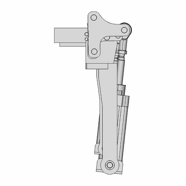
Sheet 1

Orthographic

This sheet includes 88 geometry edges from the CAD projection pipeline.

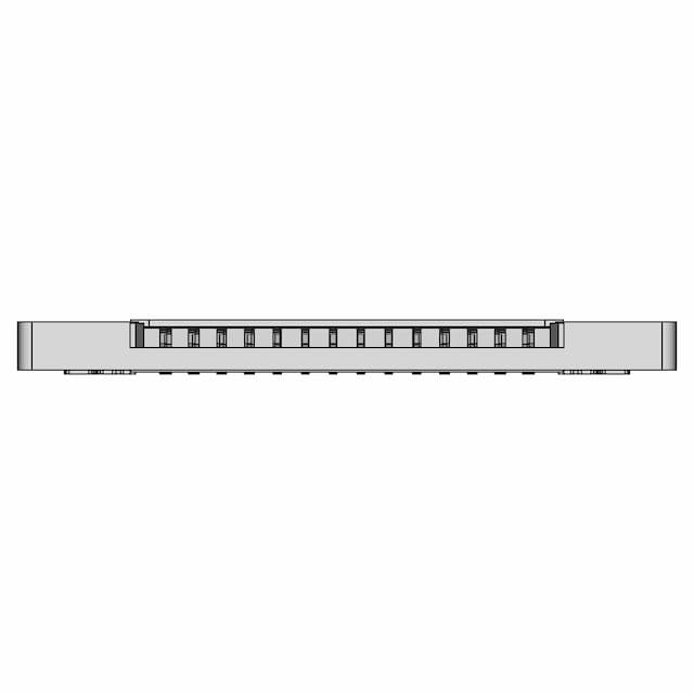
Sheet 2

Orthographic

This sheet includes 94 geometry edges from the CAD projection pipeline.

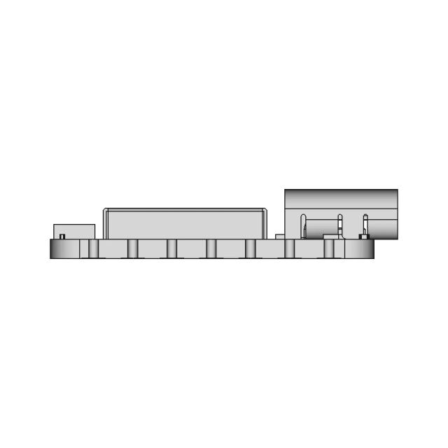
Sheet 3

Orthographic

This sheet includes 103 geometry edges from the CAD projection pipeline.

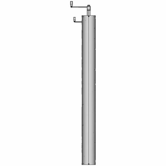
Sheet 5

Orthographic

This sheet includes 87 geometry edges from the CAD projection pipeline.

Sheet 6

Orthographic

This sheet includes 87 geometry edges from the CAD projection pipeline.

Sheet 7

Orthographic

This sheet includes 86 geometry edges from the CAD projection pipeline.

Sheet 8

Orthographic

This sheet includes 91 geometry edges from the CAD projection pipeline.

Sheet 9

Orthographic

This sheet includes 86 geometry edges from the CAD projection pipeline.

Sheet 10

Orthographic

This sheet includes 86 geometry edges from the CAD projection pipeline.

Sheet 5section_a · Section5
sheet_num: 5 · edges: 87

Sheet 5. Geometry is derived from the 3D model projection for this drawing set.

  • 87 resolved edges in sheet geometry
  • See technical_drawing_simple.pdf, sheet_N.pdf, and svg/ for full graphical context
  • Verify critical dimensions against the source CAD before manufacturing
Sheet 6section_b · Section6
sheet_num: 6 · edges: 87

Sheet 6. Geometry is derived from the 3D model projection for this drawing set.

  • 87 resolved edges in sheet geometry
  • See technical_drawing_simple.pdf, sheet_N.pdf, and svg/ for full graphical context
  • Verify critical dimensions against the source CAD before manufacturing
Detail Cdetail_c · base_view: Left
anchor: (0, 0, 0) · radius: 20

Magnifies the gear teeth and the pivot point of the linkage to show precise engagement and tolerances.

  • Detail-view anchor selected by the AI planning stage
  • Use with sheet PDF/SVG for local feature inspection
  • Validate critical dimensions against source CAD before release
Detail Ddetail_d · base_view: Top
anchor: (0, 0, 0) · radius: 20

Highlights the handwheel's hub and the mounting bolts to ensure proper alignment and torque specifications.

  • Detail-view anchor selected by the AI planning stage
  • Use with sheet PDF/SVG for local feature inspection
  • Validate critical dimensions against source CAD before release

Downloads

Download Individual Sheets

Each sheet available in PDF, SVG, and DXF. Click a format badge to download.

Sheet 1
Sheet 2
Sheet 3
Sheet 5
Sheet 6
Sheet 7
Sheet 8
Sheet 9
Sheet 10

Drawing report

Drawing details & review

Cover summary and review report for this versioned drawing set.

TECHNICAL DRAWING

6980c2a1a96c6aa4270c1397

Tilting Drawing Table

8
sheets
5
control frames
0
dimensions not drawn
Sheet index
SheetViewScaleContent
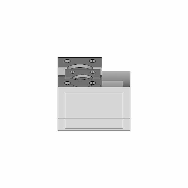
1Assembly - Front View0.5standard_view
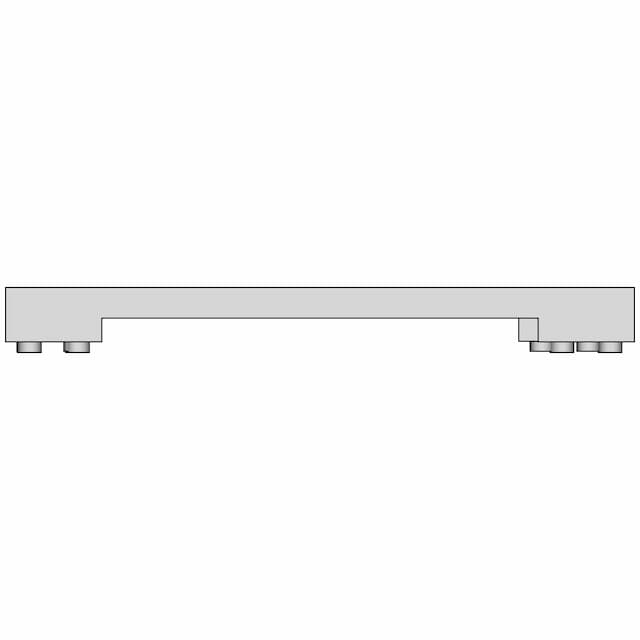
2Assembly - Top View0.47000000000000003standard_view
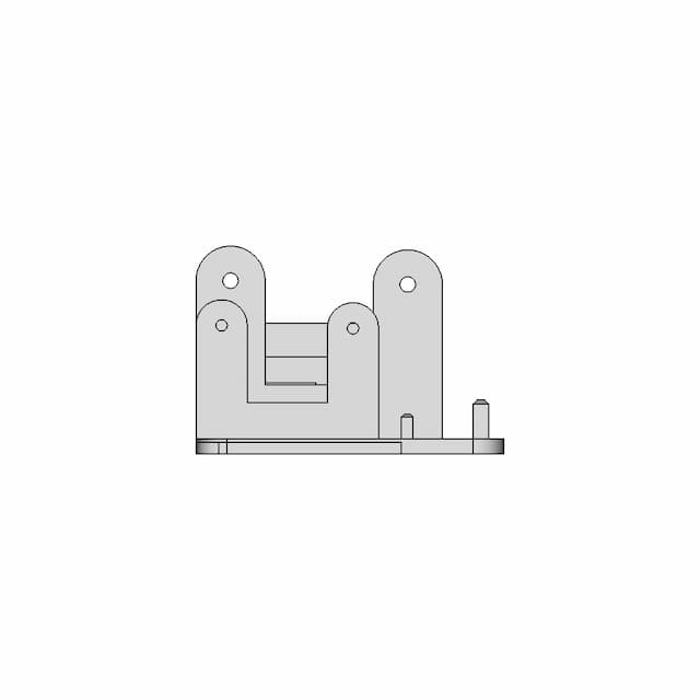
3Assembly - Left View0.5standard_view
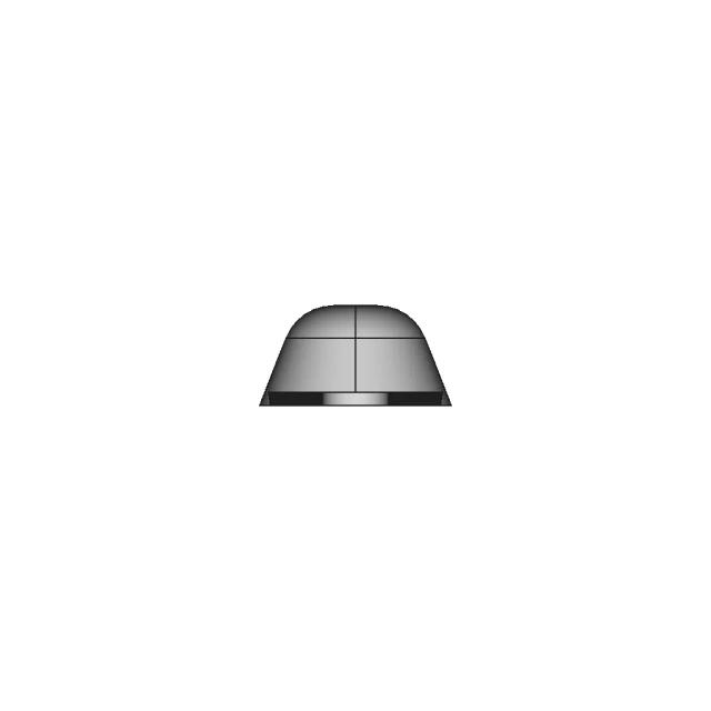
4Assembly - Isometric View0.25standard_view
5Section A-A0.5section_view
6Section B-B0.5section_view
7Detail C2.0detail_view
8Detail D2.0detail_view

Generated automatically and intended for review before use. A companion review report lists what needs checking.

DRAWING REVIEW REPORT

6980c2a1a96c6aa4270c1397

This drawing is generated automatically and is a first draft. The items below need a human decision.

Summary
54
dimensions drawn
0
selected, not drawn
5
control frames
3
assumed tolerances
Tolerances to verify
CharacteristicTolDatumsConfidenceReason
position1.0A | B | Cmediumbolt/hole pattern × 16 (position)
position1.0A | B | Cmediumbolt/hole pattern × 12 (position)
position0.75A | B | Cmediumbolt/hole pattern × 8 (position)
Tolerance schedule
CharacteristicTolZoneDatumsConfidence
flatness0.3high
perpendicularity0.3Ahigh
position1.0diameterA | B | Cmedium
position0.75diameterA | B | Cmedium
Dimension schedule

All 54 dimension(s) drawn.

#SheetTypeValueDescription
11DistanceX1500.0overall width 1500.0mm
21DistanceY674.0overall height 674.0mm
31Radius0.68x R0.6mm
41DistanceX1050.0width 1050.0mm at y≈-135.0mm [unverified span]
51DistanceX1038.8width 1038.8mm at y≈-112.5mm [unverified span]
61DistanceX762.0hole pitch 762.0mm (2 x Ø50, from model)
72DistanceX1500.0overall width 1500.0mm
82DistanceY1257.7overall height 1257.7mm
92Radius14.4R14.4mm
102Radius25.08x R25.0mm
112Radius45.04x R45.0mm
122DistanceX762.0hole pattern width 762.0mm (4 x Ø16, from model)
133DistanceX1257.7overall width 1257.7mm
143Diameter17.34x Ø17.3mm
153Diameter20.34x Ø20.3mm
163DistanceY268.0hole pitch 268.0mm (vertical, Ø17.3)
173DistanceY268.0hole pitch 268.0mm (vertical, Ø30)
183DistanceX551.4hole pitch 551.4mm (horizontal, Ø17.3)
193Radius24.898x R24.8mm
203Angle15.6999999999999892x angle 15.7 deg
213Angle34.5angle 34.5 deg
223Distance280.0hole pitch 280.0mm (2 x Ø16, from model)
235DistanceX1257.7overall width 1257.7mm
245DistanceY674.0overall height 674.0mm
255Diameter16.02x Ø16.0mm
265DistanceY268.0hole pitch 268.0mm (vertical, Ø30)
275Radius40.04x R40.0mm
285Radius45.02x R45.0mm
295Angle86.22x angle 86.2 deg
305Angle34.5angle 34.5 deg
315Distance280.0hole pitch 280.0mm (2 x Ø16, from model)
326DistanceX1257.7overall width 1257.7mm
336DistanceY674.0overall height 674.0mm
346Diameter16.02x Ø16.0mm
356DistanceY268.0hole pitch 268.0mm (vertical, Ø30)
366Radius40.04x R40.0mm
376Radius45.02x R45.0mm
386Angle86.22x angle 86.2 deg
396Angle34.5angle 34.5 deg
406Distance280.0hole pitch 280.0mm (2 x Ø16, from model)
417Diameter20.0Ø20.0mm
427Diameter40.8Ø40.8mm
437Diameter42.0Ø42.0mm
447Radius2.927x R2.9mm
458Diameter14.0Ø14.0mm
468Diameter20.0Ø20.0mm
479Diameter20.0Ø20.0mm
489Diameter40.8Ø40.8mm
499Diameter42.0Ø42.0mm
509Radius2.927x R2.9mm
5110Diameter20.0Ø20.0mm
5210Diameter40.8Ø40.8mm
5310Diameter42.0Ø42.0mm
5410Radius2.927x R2.9mm

Paid Pipeline · $5.99 per drawing set

Have your own 3D CAD file?

Upload a STEP or STP file and generate a 2D drawing set with PDF, SVG and DXF outputs.

  • ✓ Usually ready in minutes
  • ✓ 9 sheets · editable FCStd + PDF, SVG, DXF
  • ✓ No subscription · pay per file
$5.99
per drawing set incl. GST
4 min
avg. turnaround

AI Transparency

How these drawings were generated

These drawings were generated from the source 3D CAD geometry. The system analysed the model, selected relevant views, planned section cuts and generated drawing sheets in PDF, SVG and DXF formats.

These are 2D engineering drawings, not 3D files. Dimensions are extracted from the 3D geometry and should be verified against the source model before use in manufacturing.

Run Metadata

9
Views analysed
9
Sheets generated
2
Section cuts
2
Export formats
26 Sept 2026
Generated date

Explore Marathon OS

Related resources

Jump to the source 3D model, generate your own drawings, or browse tools and libraries.

Open source 3D CAD modelPreview the original 3D geometry used to generate these drawings→
Generate your own 2D drawingUpload STEP, STP, IGES or FreeCAD — get PDF, SVG and DXF→Browse more 2D technical drawingsExplore AI-generated orthographic sheets across part types→Browse 3D CAD modelsDownload and preview open-source STEP, STL and IGES files→Open CAD files onlineView STEP, IGES, STL and more in your browser→Convert CAD files onlineConvert between STEP, STL, OBJ and other 3D formats→Get manual drafting supportWork with vetted CAD designers for production-ready drawings→

Preview the Source 3D CAD Model

Open the original 3D CAD model used to generate this 2D drawing set. Review the source geometry before downloading or using the technical drawings.

Open 3D CAD model →
Marathon Logo

The specialist CAD conversion platform for engineering, mesh and drawing workflows.

Start a conversion
ConvertAll 60+ conversion toolsSTEP to STLSTL to STEPIGES to STEPDWG to DXFSTEP or STP to 2D
Products3D CAD Products2D CAD Products
Tools and servicesAll CAD Tools3D CAD ViewerSTEP BOM ExtractorHire a CAD Designer
CompanyHomeAbout UsContact Us
LegalPrivacy PolicyTerms and ConditionsRefund Policy
© 2026 Marathon OS. All rights reserved.Convert precisely. Download confidently. Keep moving.

Recently added / Trending

Everything you need to design faster, smarter, and with more impact.
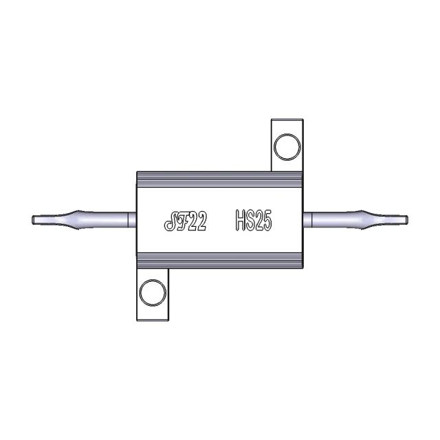
Power Resistor 25W
Power Resistor 25W
130 Meter Long Oil Tanker Shell Element Model
Pinomatik Klamp - Downloadable CAD Representation
Er-Con0.62-14P (Lw06121-14) | 3D Engineering Design File
Expert Pcb Board 1 | CAD Model for Energy Systems
Seeed Studio Xiao NRF52840 Sense
Cnc Face Plate | High-Quality CAD Model
3D CAD Model Created in SolidWorks
Archimedes Screw Pump 3 | CAD Model for Energy Systems
NACA 4415 Airfoil Wind Turbine Blade Design
View all designs

Marathon-OS Design Hub

Everything you need to design faster, smarter, and with more impact.

Triple Arm Fidget Spinner with Enhanced Grip Design
Lattice Bowl 1 | 3D CAD Engineering Model
The Bobina | 3D Engineering Design File
Origami Bird For 3D Printing 1 | 3D CAD Engineering Model
Testing Fusion Part 4 | 3D Engineering Design File
Iron Giant Scaled Model 1 | 3D CAD Engineering Model
Switchbot Smart Lock Pro Adapter 1 | 3D CAD Engineering Model
Elongated Pentagonal Gyrobirotunda 1 | 3D CAD Engineering Model
Diminished Rhombicosidodecahedron 1 | 3D CAD Engineering Model
Practice | 3D Engineering Design File
Cover Usb & Btt Tf Cloud Artillery | 3D Engineering Design File
Lego_Speed_Formula1_Wall_Mount | 3D Engineering Design File
Reinforced Coffee Dosing Spoon 3D Model
1:350 Scale Simplified Model for Efficient Printing
Prusa Nextruder Nozzle Adapter CAD Model
Tripod 1 4 20 1 6Mm Flat Board Mount 1 | 3D CAD Engineering Model
View all designs

Explore More 2D Designs

View all
BIO REACTOR, Used for CFD Analysis for Projects
2D Drawing$5.99
M12 X-CODE CAT6A Plug - High-Performance Industrial Connector
2D Drawing$5.99
M12 X-Code Connector - High-Performance Industrial Connector
2D Drawing$5.99
Toyota Hilux Double Cab 3D CAD Model for Engineering and Design
2D Drawing$5.99
Offroad Transmission Undershield for Enhanced Protection
2D Drawing$5.99
Adjustable Square and Round Tube Rock Slider for Pickup Trucks
2D Drawing$5.99
Aluminum Off-Road Front Bumper for Toyota Hilux Vigo
2D Drawing$5.99
Toyota Hilux Revo Offroad Bumper 4x4 Concept 3D Model
2D Drawing$5.99